Seismic risk cannot be ignored — system bracing is critical to MEP safety

Without continuous restraint and reliable anchorage, MEP piping and equipment can fall, collide, lose function, or trigger secondary disasters under seismic action. Systematic bracing is essential to building MEP safety.

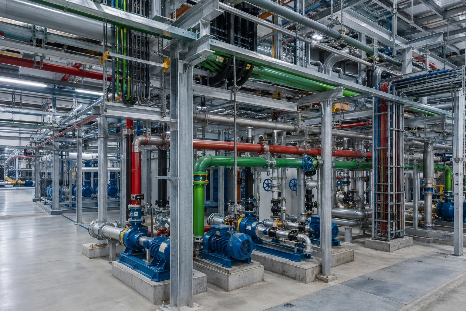
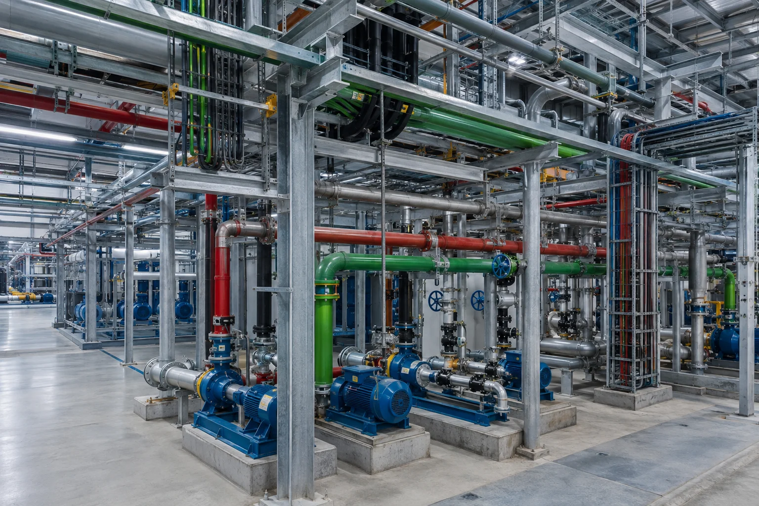
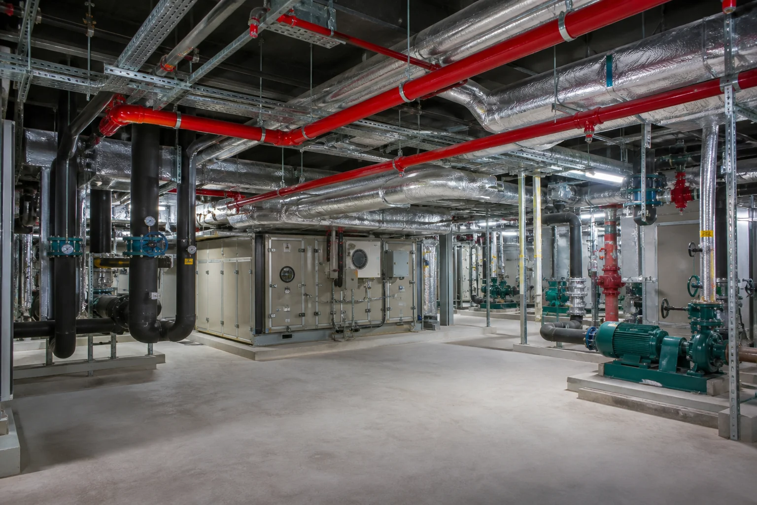
MEP equipment and piping installation scene

Equipment fall

Seismic forces can cause support failure and equipment drop, leading to injury and property loss.
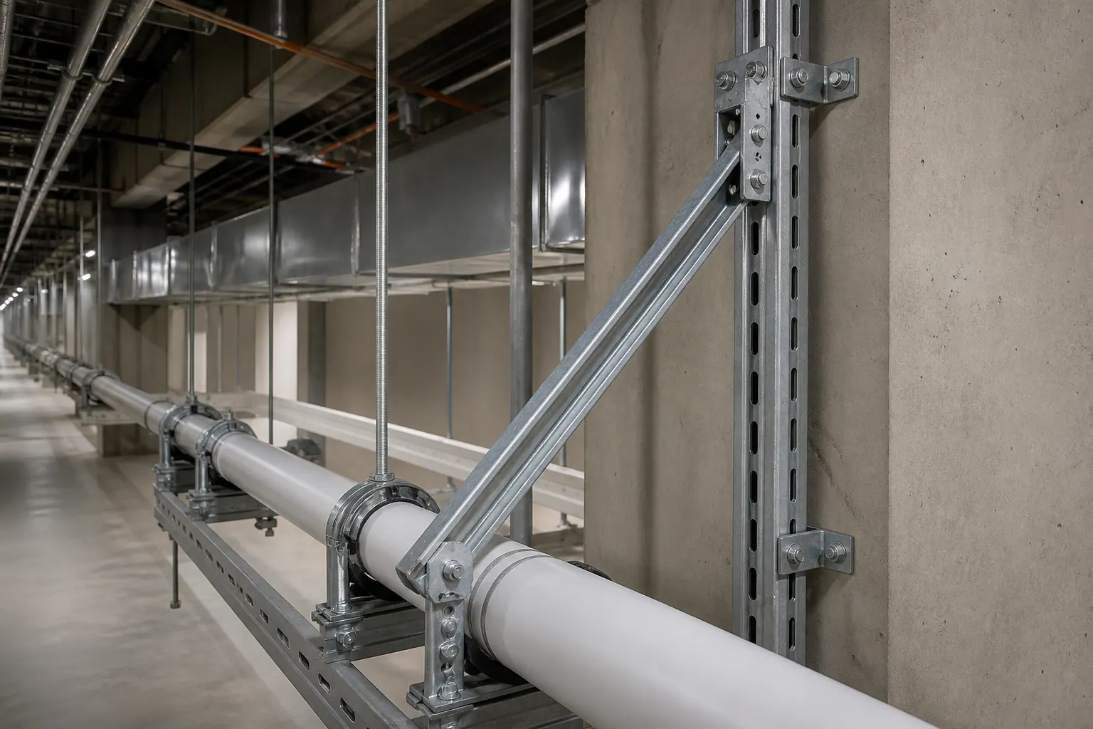
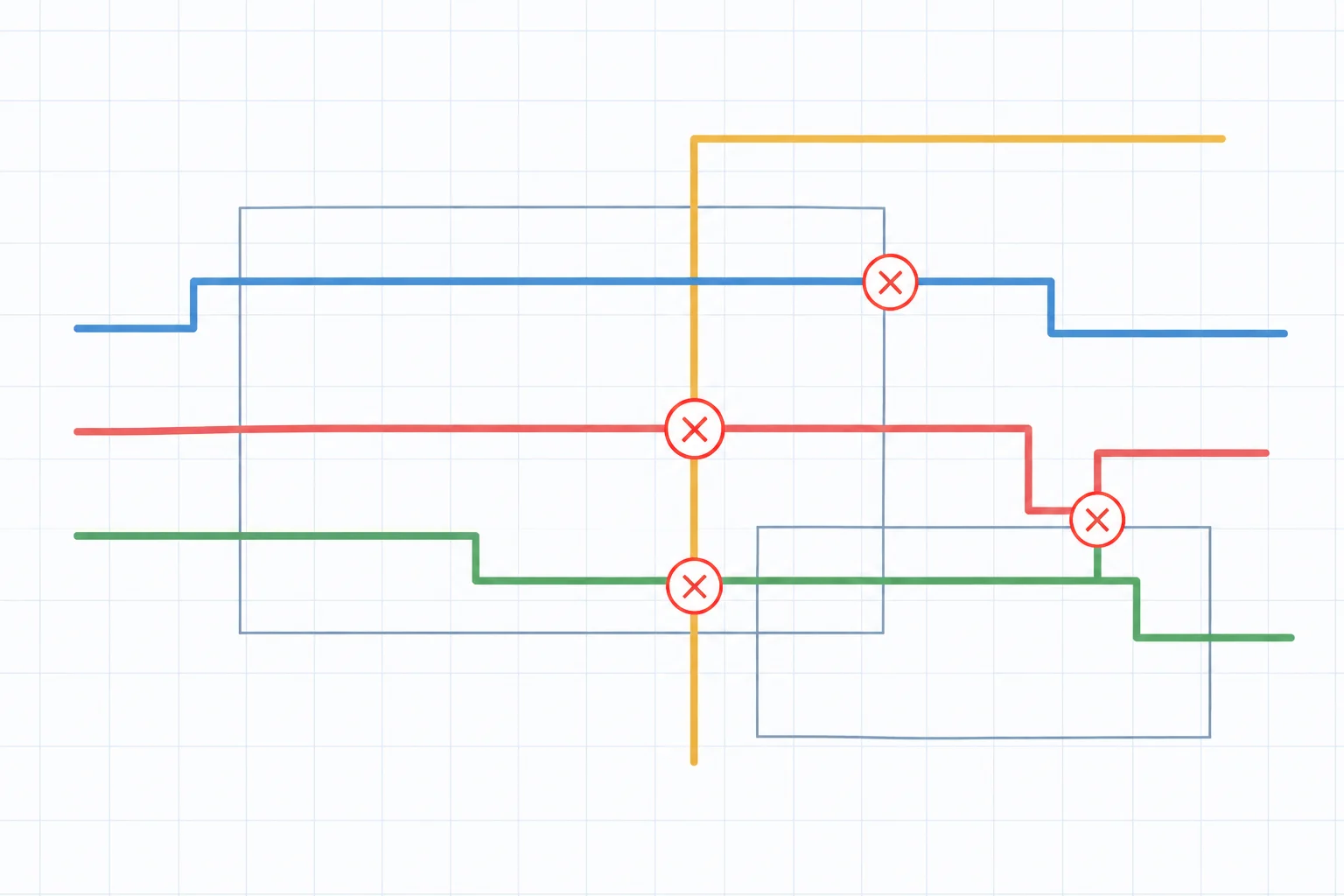
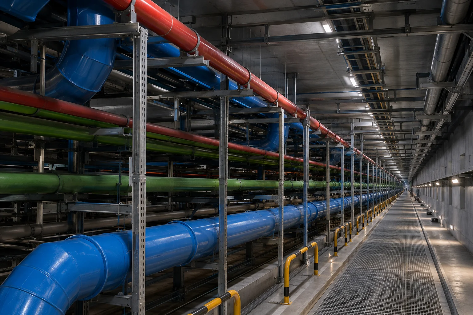
MEP piping coordination scene

Pipeline collision

Displacement can cause pipes to collide, resulting in rupture, leakage, or joint damage.
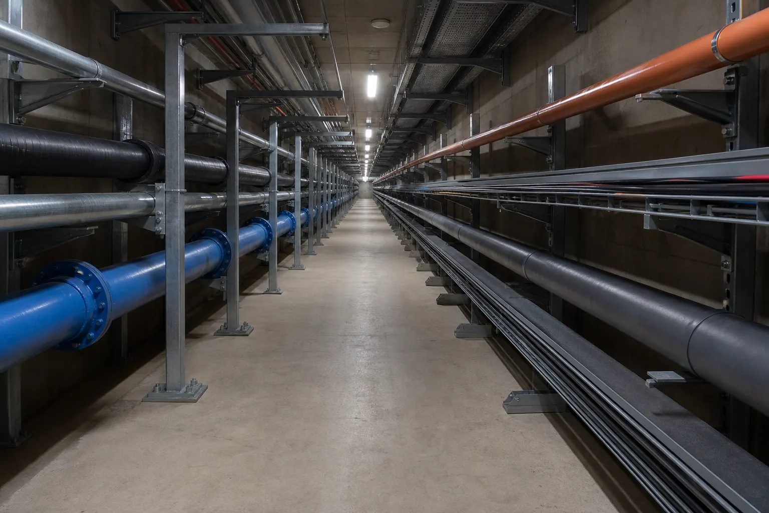
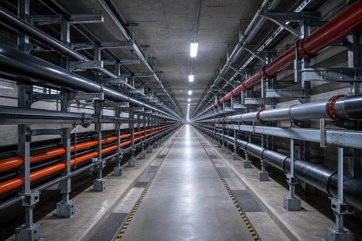
Integrated piping and support scene

Function interruption

Critical MEP systems may fail, compromising post-earthquake building usability.
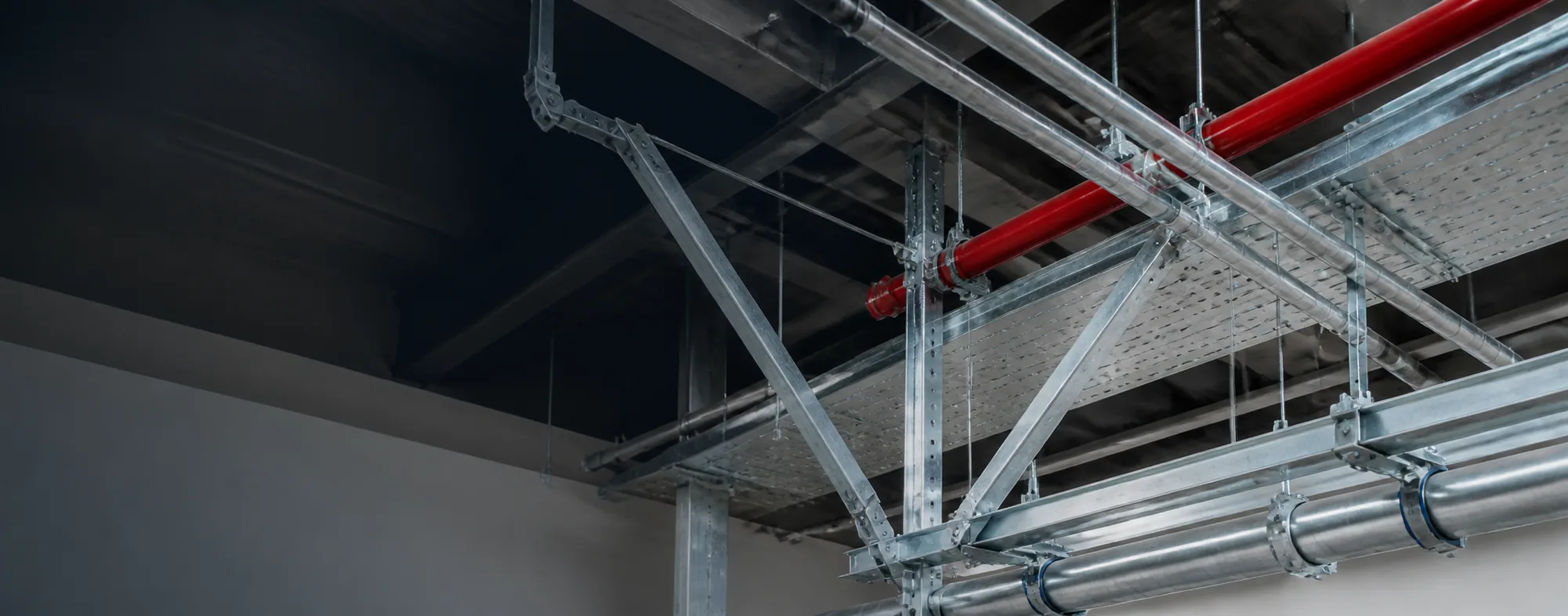
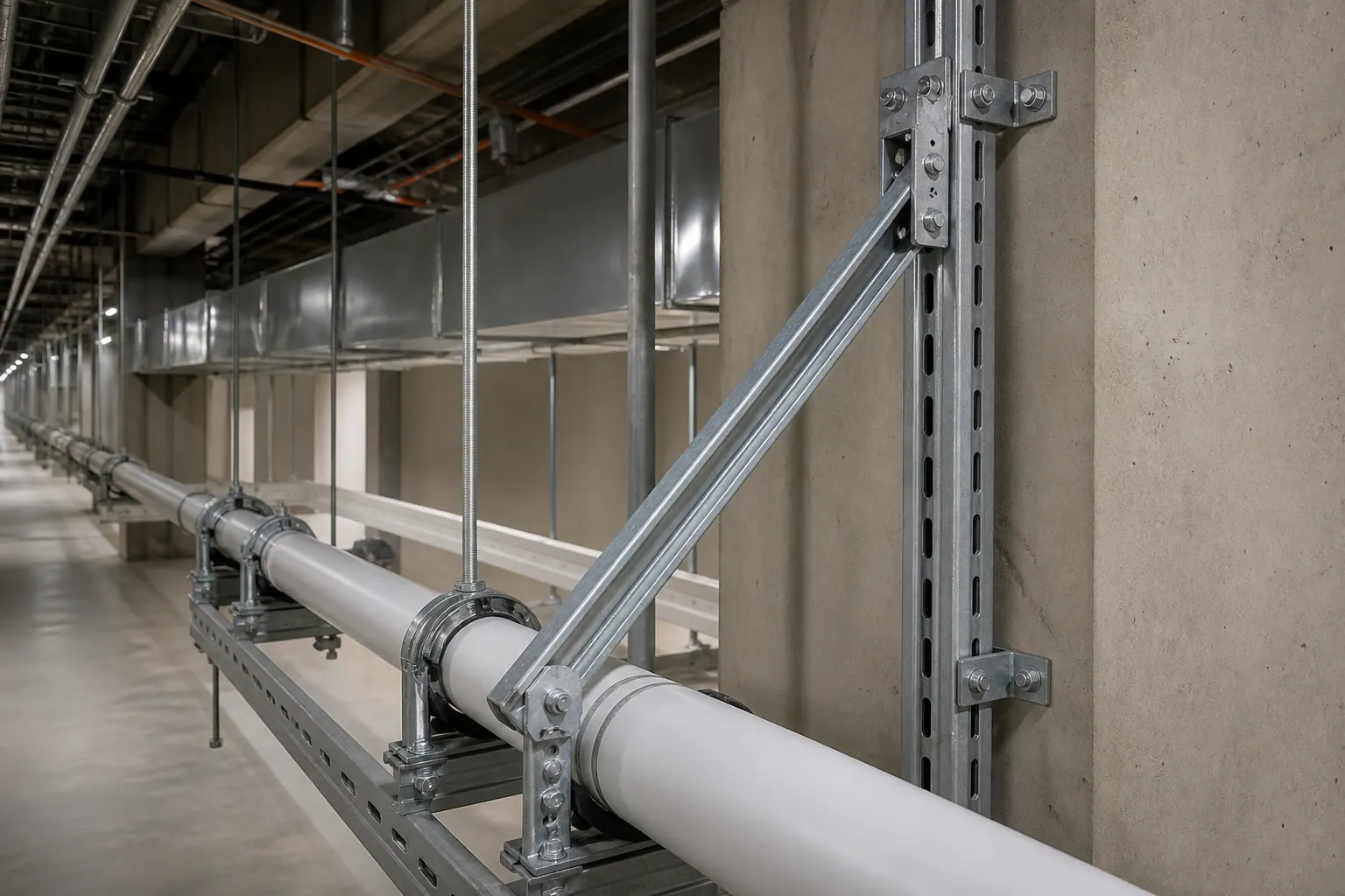
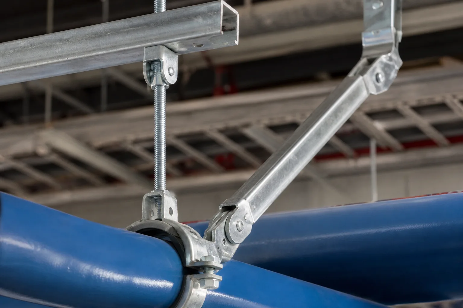
Seismic brace and piping connection scene

Secondary disasters

Leakage from fire or water systems may trigger fire, water damage, and other secondary hazards.

Broad application scenarios and system coverage

Covers major building MEP systems across healthcare, commercial, education, industrial, public, and transit facilities.
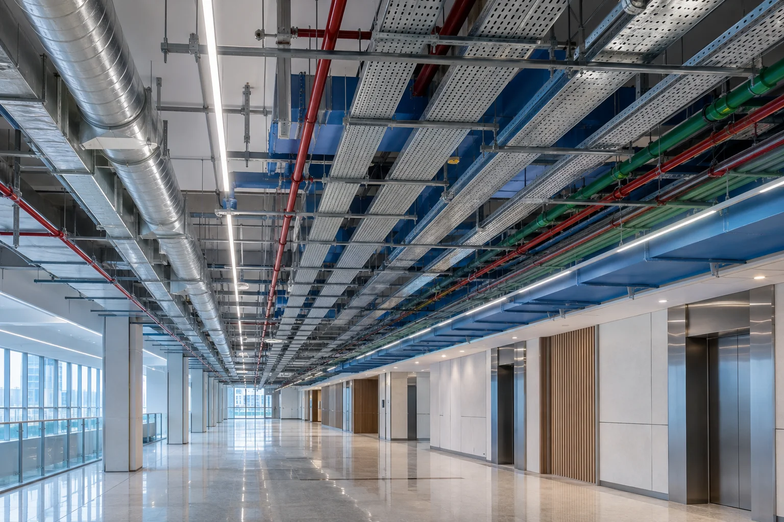
  • Plumbing
  • Fire piping
  • HVAC
  • Cable tray
  • Equipment supports
  • Combined racks
Healthcare MEP scenario
Healthcare
Commercial complex scenario
Commercial complex
Education building scenario
Education
Industrial plant MEP scenario
Industrial plant
Public building scenario
Public buildings
Rail transit MEP scenario
Rail transit

From project inputs to engineering deliverables

  1. Project drawings and condition input

    01 Project condition input

    • Building function and seismic criteria
    • MEP system classification and sizes
    • Structure and anchorage substrate data
    • Project goals and delivery boundary
  2. MEP system 3D model analysis

    02 System identification & analysis

    • Classify system objects
    • Analyze support type and spacing
    • Check clearances and clashes
    • Map critical routes and interfaces
  3. Seismic bracing detailed design

    03 Detailed design development

    • Develop seismic support layout
    • Force calculation and node design
    • BIM optimization and coordination
    • Preliminary BOM output
  4. On-site engineering delivery

    04 Engineering delivery

    • Construction and detail drawings
    • Quality and traceability documents
    • On-site installation support
    • As-built documentation handover

Four-step engineering route in a closed loop

01

Early preparation

Confirm site seismic criteria, MEP scope, and project documentation readiness.

02

Structural design

Support layout, force calculation, node detailing, and drawing/BOM output.
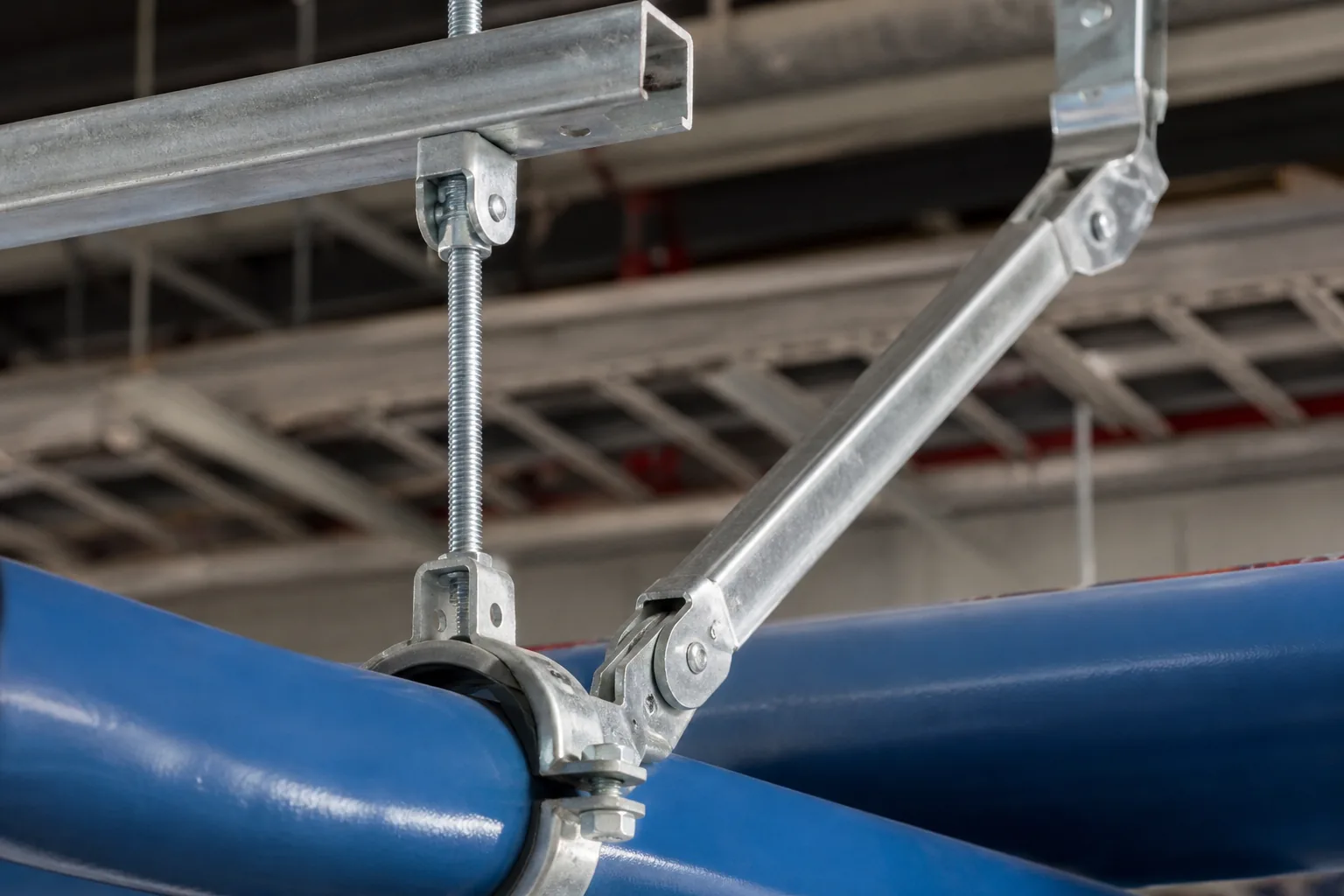
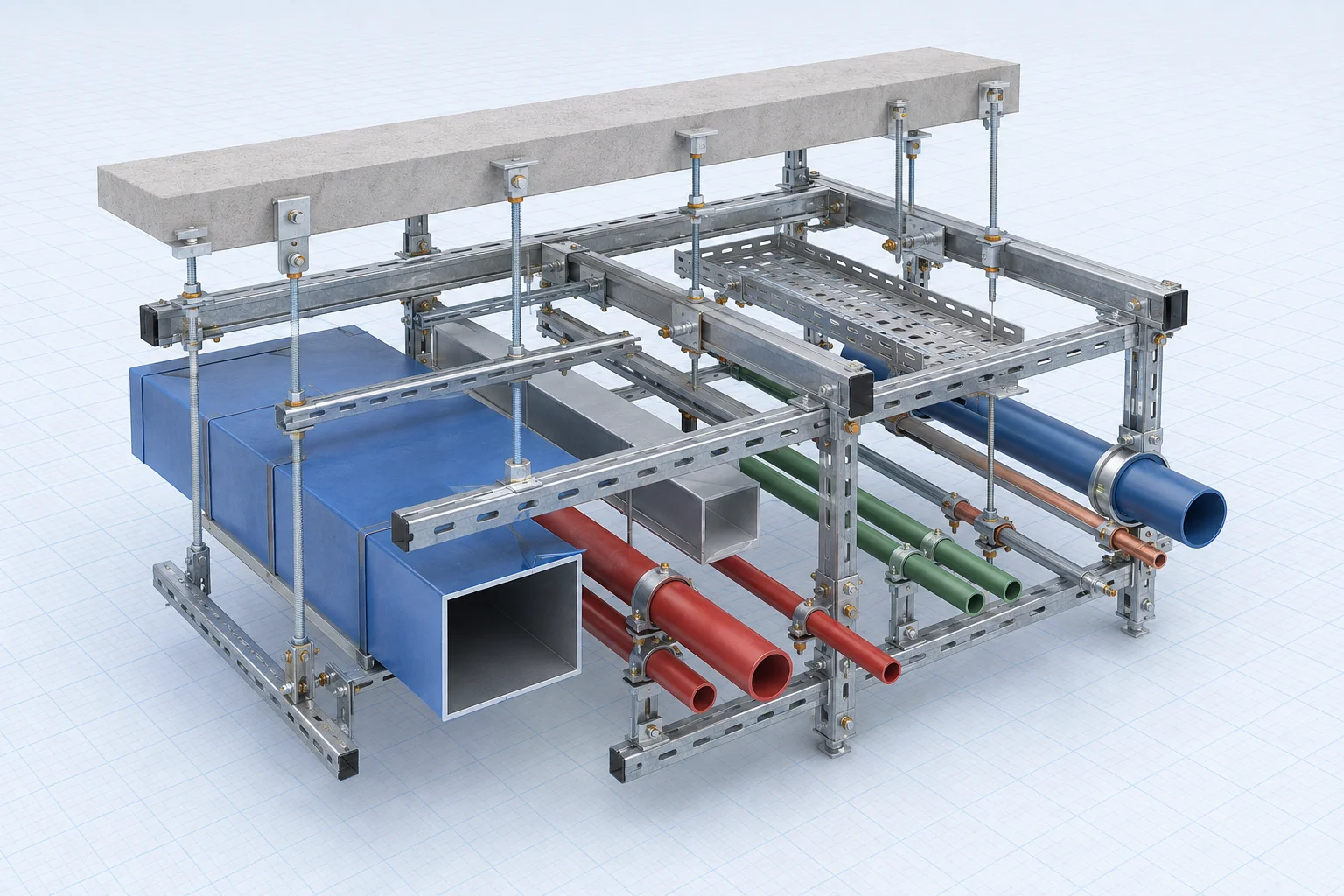
Modular seismic brace and piping assembly
03

Manufacture & supply

Standardized component production, factory QC, and staged site logistics.

04

Installation & acceptance

Installation guidance, system checks, acceptance, and O&M document handover.

Four steps linked · Concurrent design · Coordinated delivery · Assured safety
Modular seismic supports and system selection

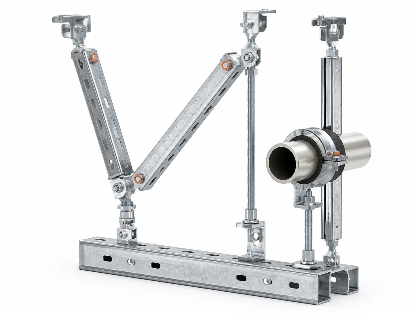
Modular seismic support assembly
  • Anchorage set
  • Reinforcing connector
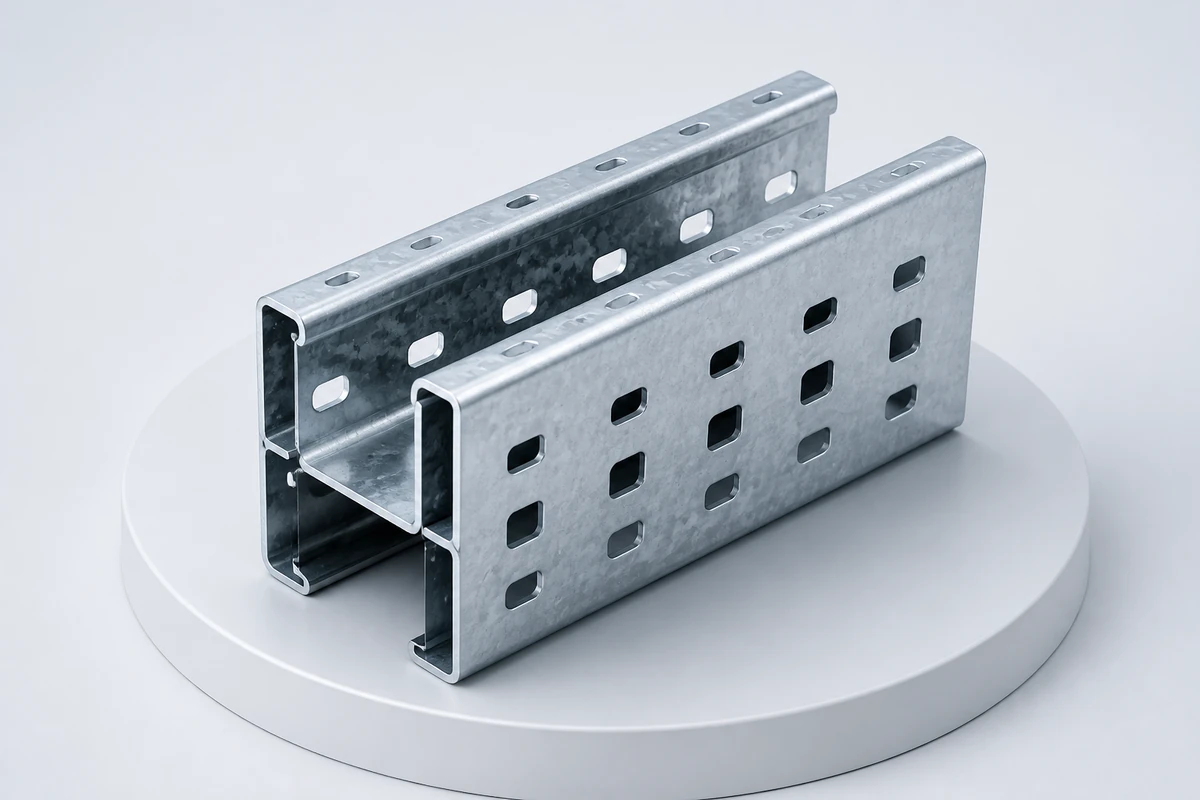
  • Channel main member
  • Clamp / clevis
  • Base & anchorage

BIM / calculation / drawings / BOM consistency

One data source links models, calculations, node details, and material lists to reduce fragmentation and rework.
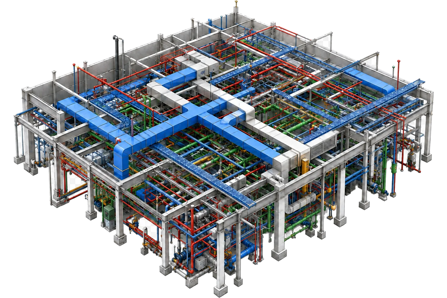
  • BIM model aligned with site conditions
  • Force calculation aligned with layout
  • Node details aligned with component specs
  • BOM aligned with drawing references
  • Change loop fully traceable
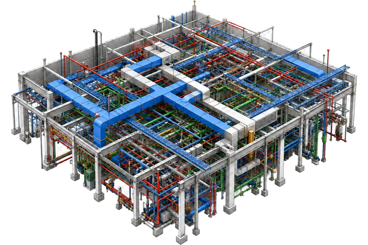
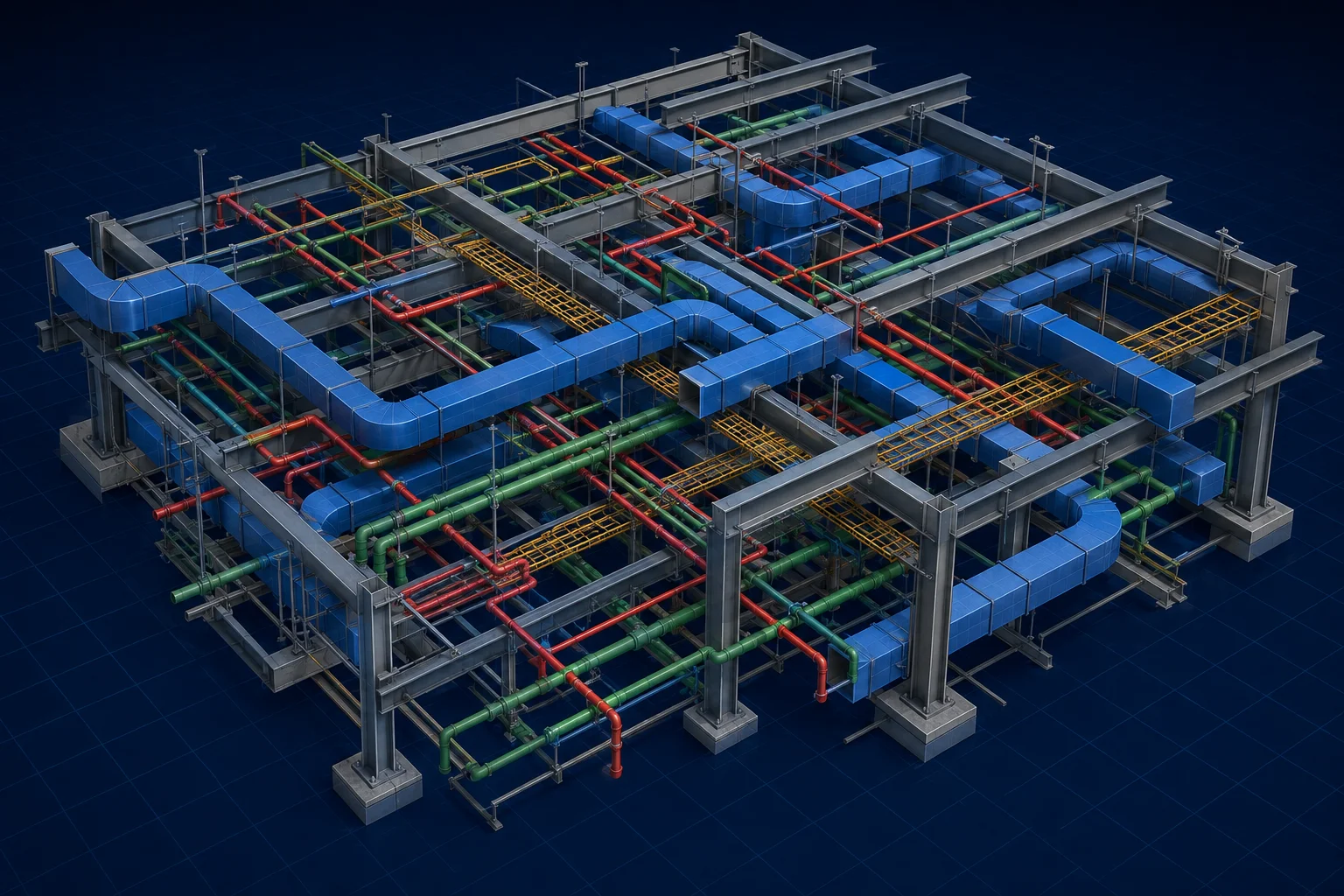
MEP seismic BIM combined model Combined MEP model

Complete load path

  • Pipe & clamp
  • Support connector
  • Diagonal brace
  • Connector
  • Anchorage
  • Building structure

Special nodes and risk control

Ends, equipment interfaces, multi-trade crossings, and high-risk zones need dedicated controls so local failure does not break the full system path.
End node illustration
End node
Post and hanger node
Post / hanger
Equipment interface node
Equipment interface
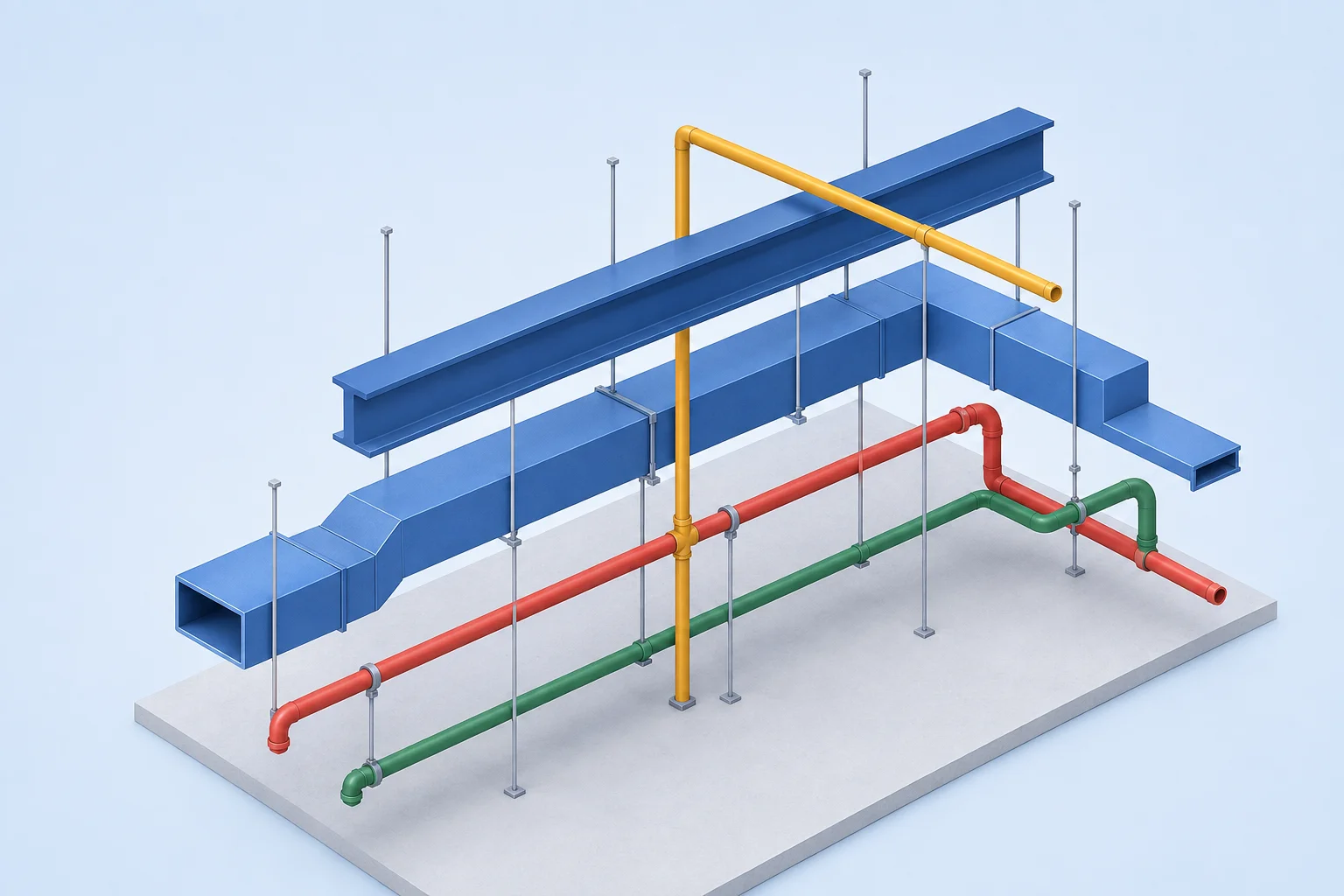
Multi-trade crossing node
Multi-trade crossing
High-risk zone node
High-risk zone

Project delivery and services

Ten linked nodes from kickoff to O&M across design, manufacturing, and site coordination.

  1. Kickoff Confirm scope boundary
  2. Concept design System & support scheme
  3. Force calc. Actions and checks
  4. BIM detailing Model & clash resolve
  5. Shop drawings Layout & node details
  6. Material list BOM and kits
  7. Manufacturing Fabrication & QC
  8. Site install Guidance & coordination
  9. Acceptance Docs & site verify
  10. O&M Support & traceability

Need detailing for a building MEP seismic project?

Full-process technical support from condition review and detailed design to manufacturing delivery and on-site assistance.