


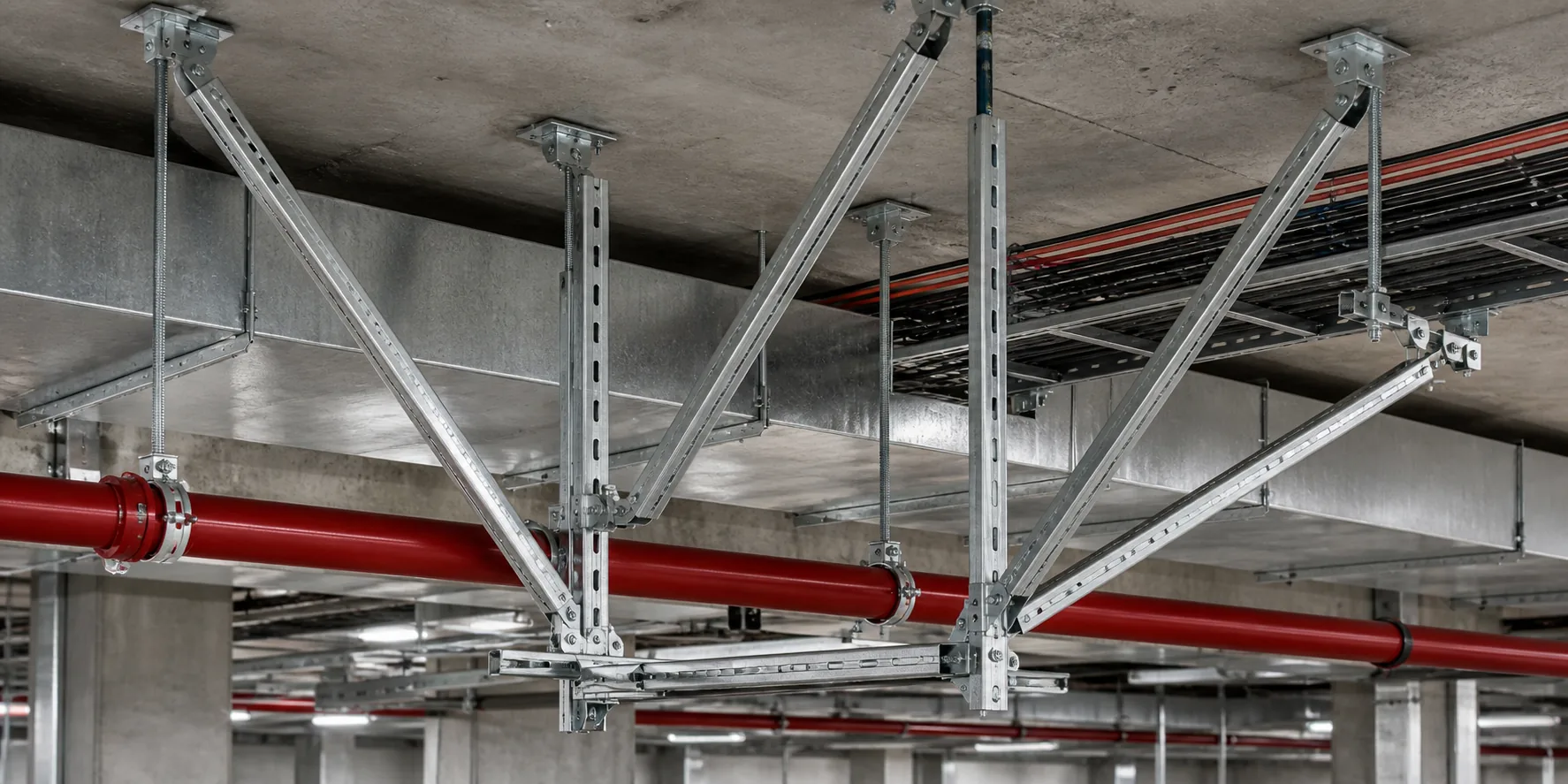
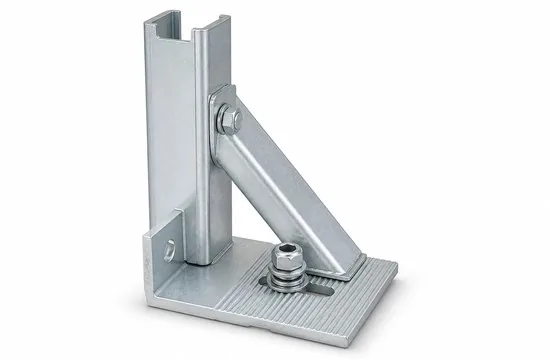
Clear load path
Spring nuts, bolts and washers for channel assembly.
Spring nuts, bolts and washers for channel assembly.
SE-CONNECT-09 belongs to the Seismic Connectors product family.
The product image and published category data are provided as a starting point; interfaces, dimensions and final configuration remain project-specific.
Final values follow confirmed project drawings, calculations and BOM.
Spring nuts, bolts and washers for channel assembly.
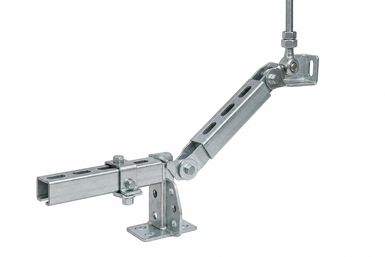
Category-level reference image; confirm the exact member, interface and dimensions for this model against project drawings.
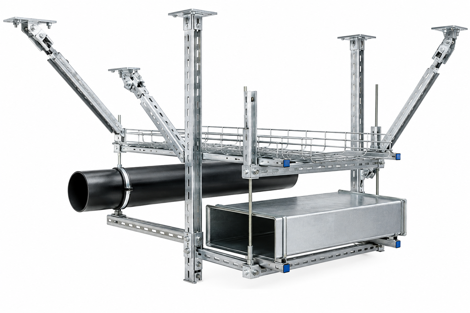
Category-level reference image; confirm the exact member, interface and dimensions for this model against project drawings.
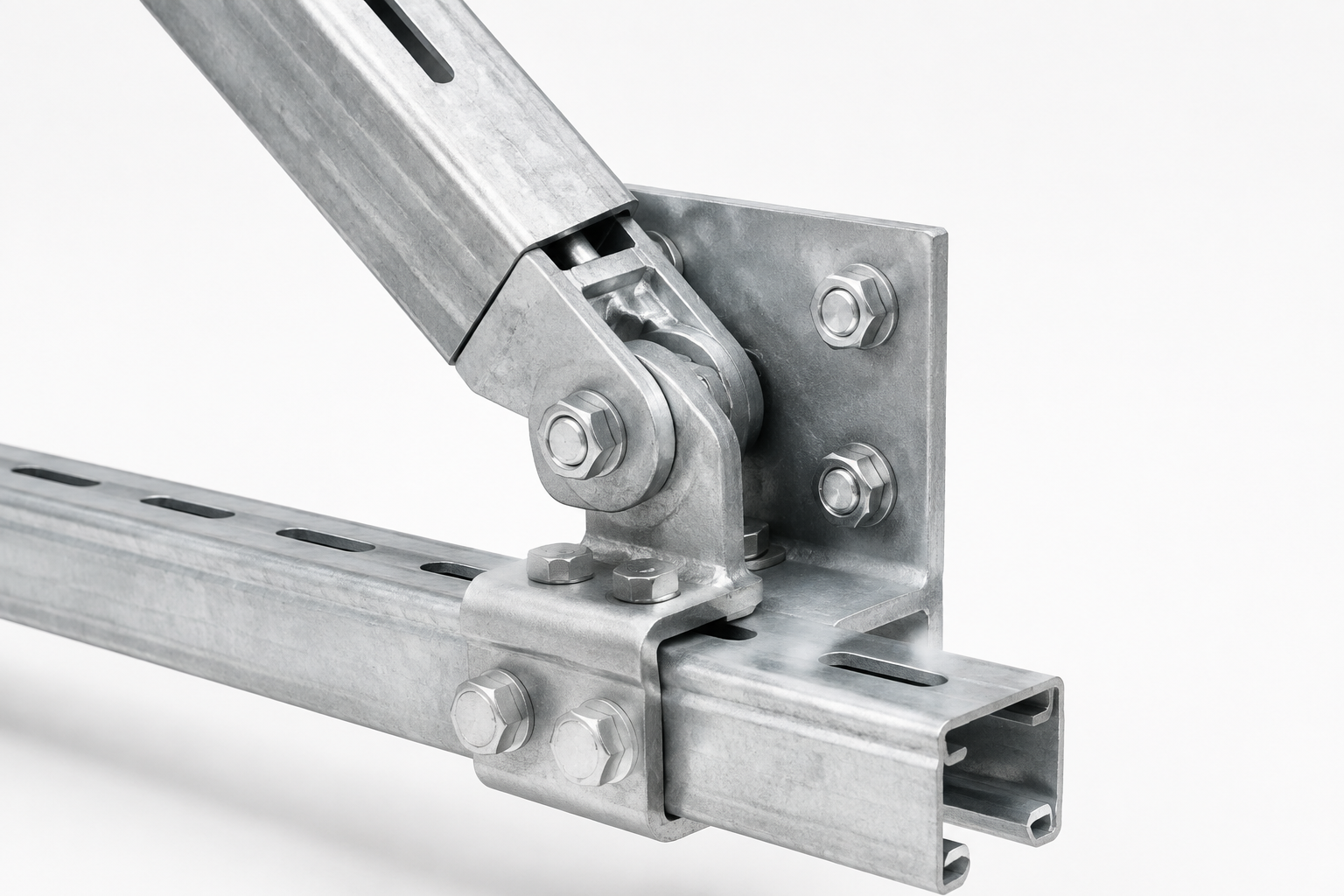
Category-level reference image; confirm the exact member, interface and dimensions for this model against project drawings.
Organize the system around load-bearing members, seismic braces, connectors, equipment interfaces, anchorage and load transfer.
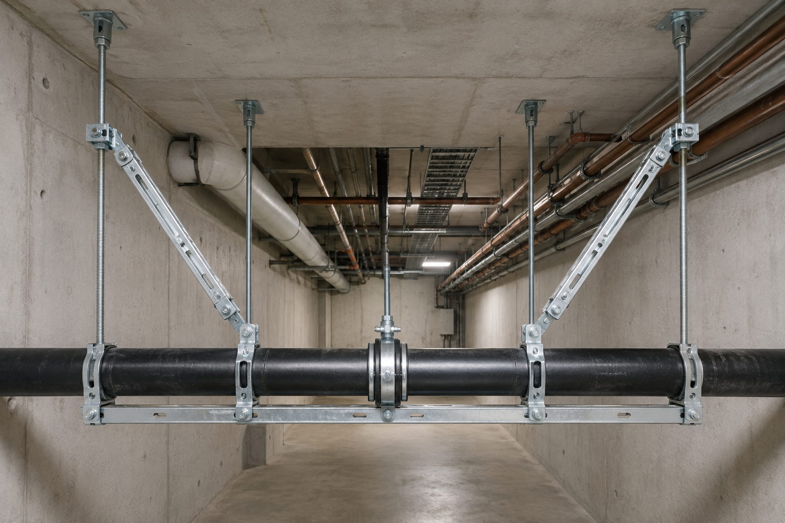
Category-level reference image; confirm the exact member, interface and dimensions for this model against project drawings.
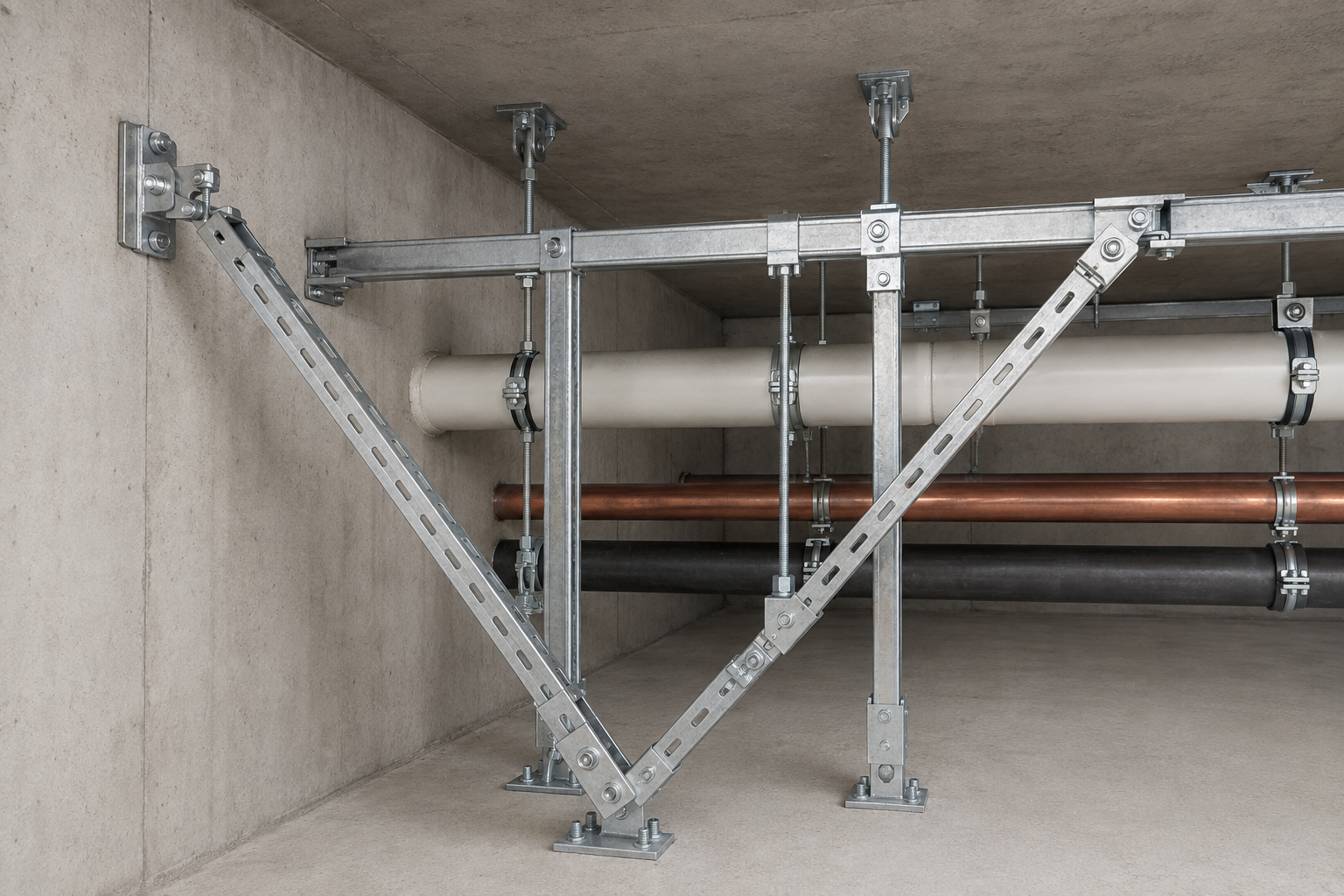
Category-level reference image; confirm the exact member, interface and dimensions for this model against project drawings.
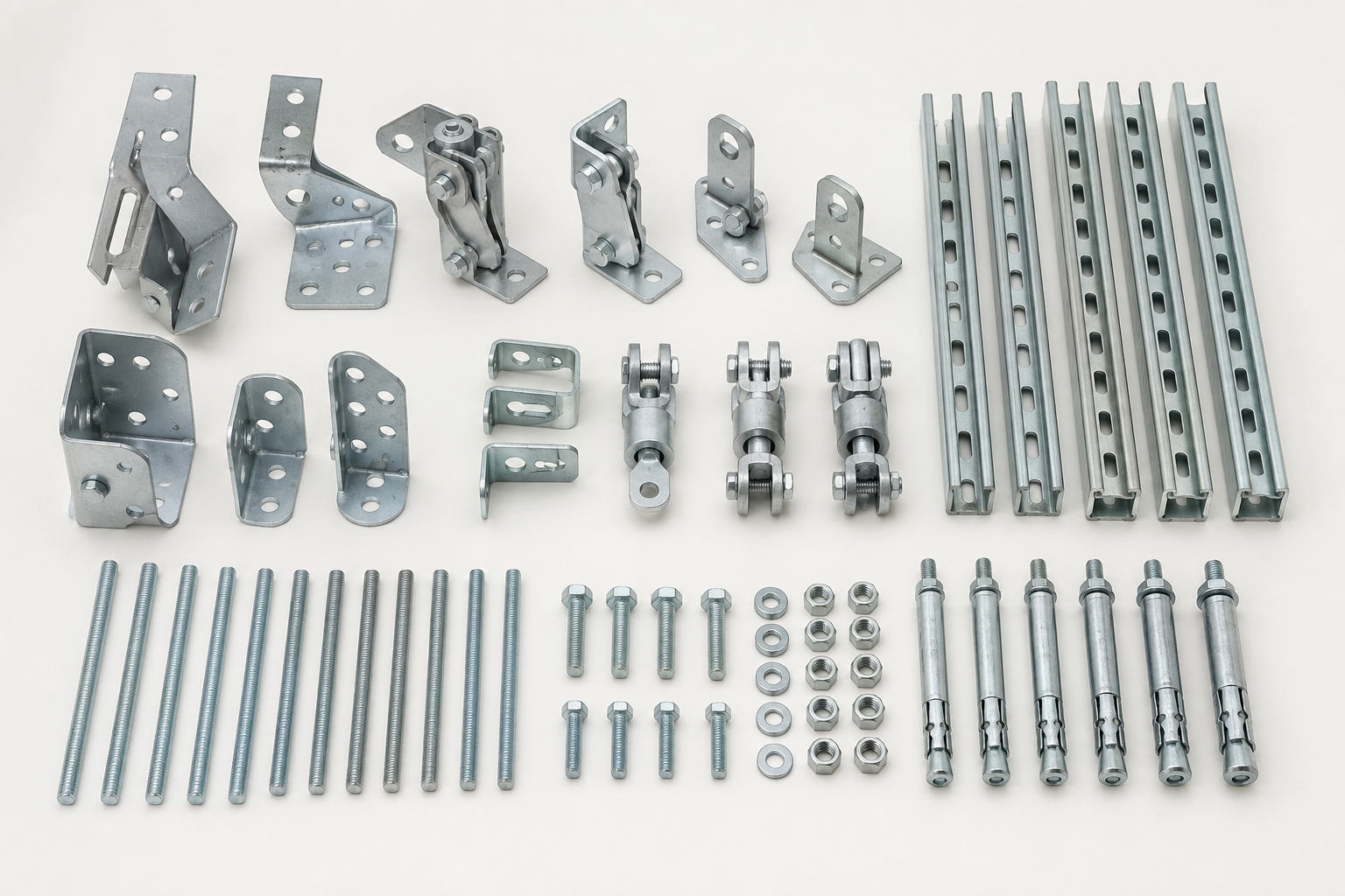
Category-level reference image; confirm the exact member, interface and dimensions for this model against project drawings.
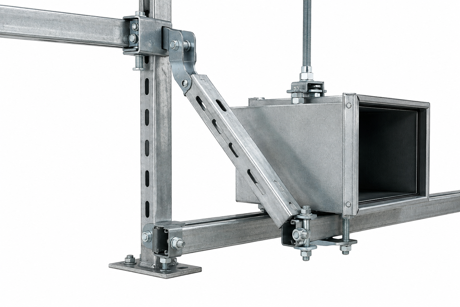
Category-level reference image; confirm the exact member, interface and dimensions for this model against project drawings.
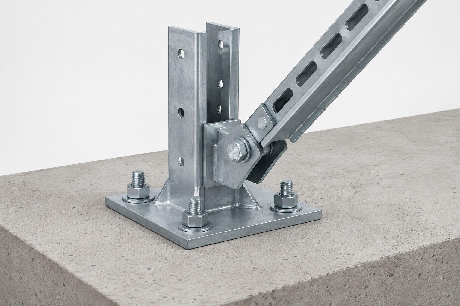
Category-level reference image; confirm the exact member, interface and dimensions for this model against project drawings.
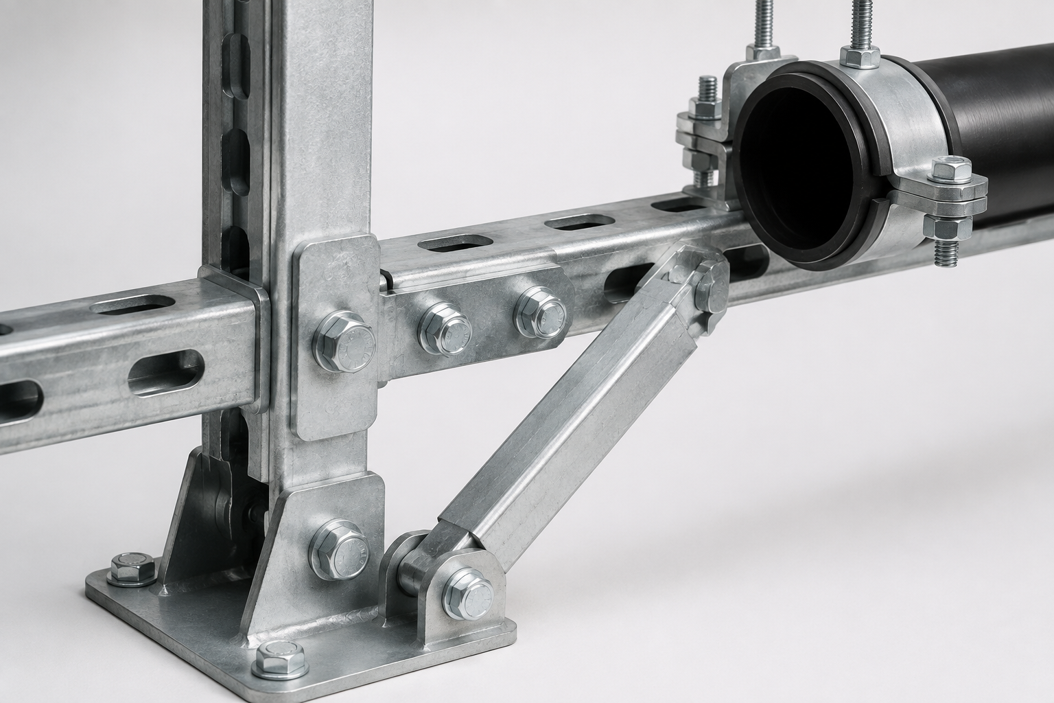
Category-level reference image; confirm the exact member, interface and dimensions for this model against project drawings.
Node images are reserved for later confirmed project or technical assets.
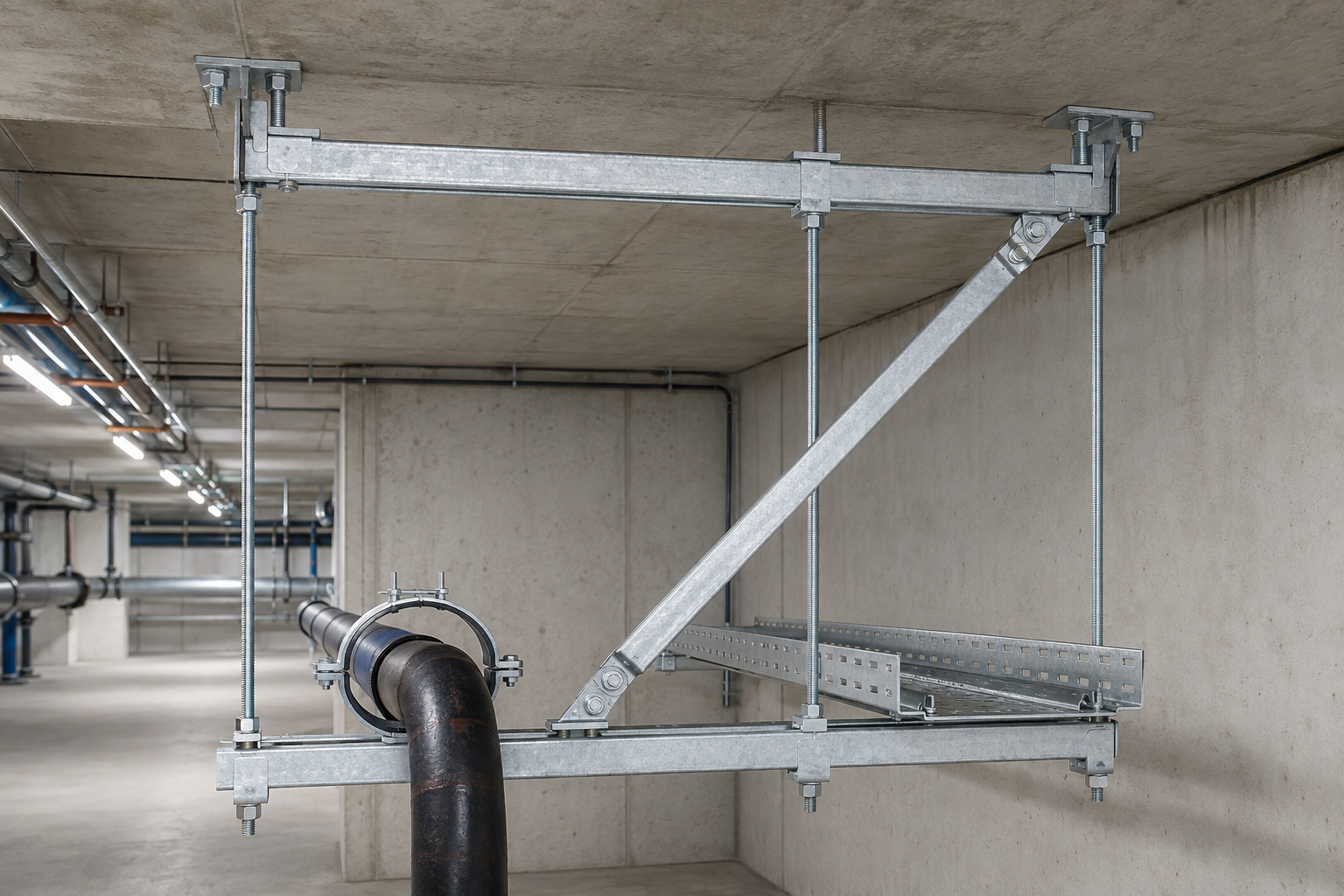
Category-level reference image; confirm the exact member, interface and dimensions for this model against project drawings.
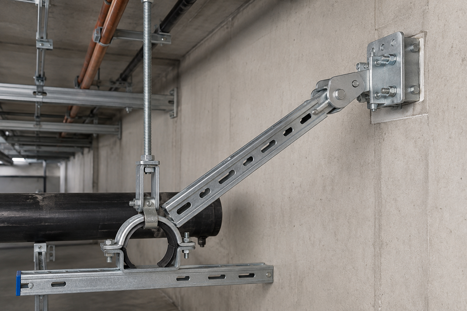
Category-level reference image; confirm the exact member, interface and dimensions for this model against project drawings.
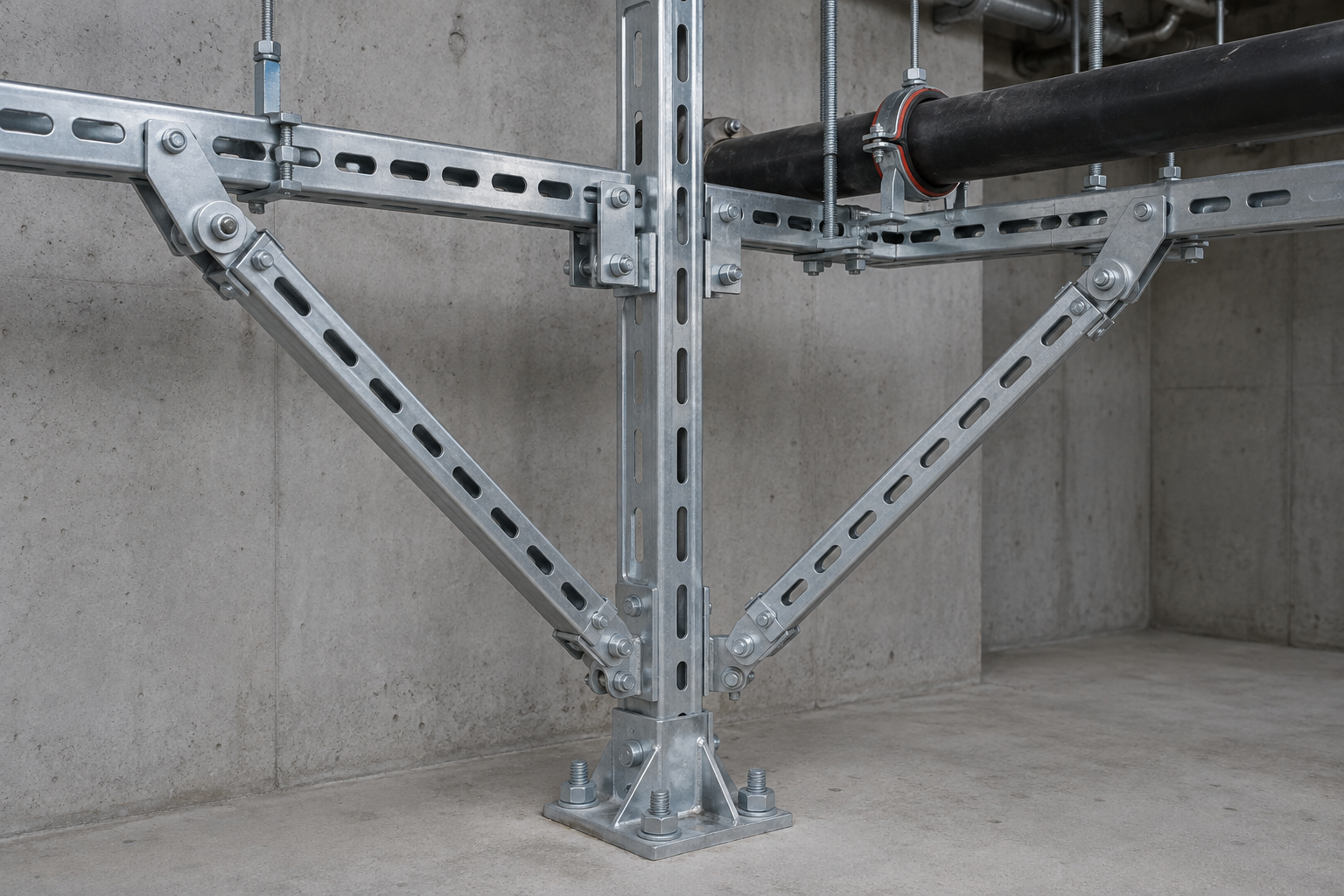
Category-level reference image; confirm the exact member, interface and dimensions for this model against project drawings.
Key reference fields for Channel Spring-Nut Kit; final values follow project confirmation.
| Parameter | Value / reference | Engineering control | Data status |
|---|---|---|---|
| Product code | SE-CONNECT-09 | Used for drawings, BOM and enquiry identification | Review placeholder |
| Reference model | SYS-SE-N09 | Confirm against the series and project configuration | Review placeholder |
| Structure | Project-specific structure and connection arrangement | Confirm by project drawings / calculations | Review placeholder |
| Main materials | Confirm by project drawings and calculations | Confirm by project drawings / BOM | Review placeholder |
| Application boundary | Project-specific use and installation conditions | Confirm during enquiry | Review placeholder |
This Channel Spring-Nut Kit (SE-CONNECT-09) page is a category-template migration draft. Unlisted values remain to be confirmed during enquiry.
| Selection item | Product reference | Engineering confirmation |
|---|---|---|
| Product code | SE-CONNECT-09 | Used for drawings and enquiry |
| Reference model | SYS-SE-N09 | Confirm by project |
| Structure / interface | Project-specific | Confirm by drawings |
Final specifications follow confirmed project drawings and calculations.
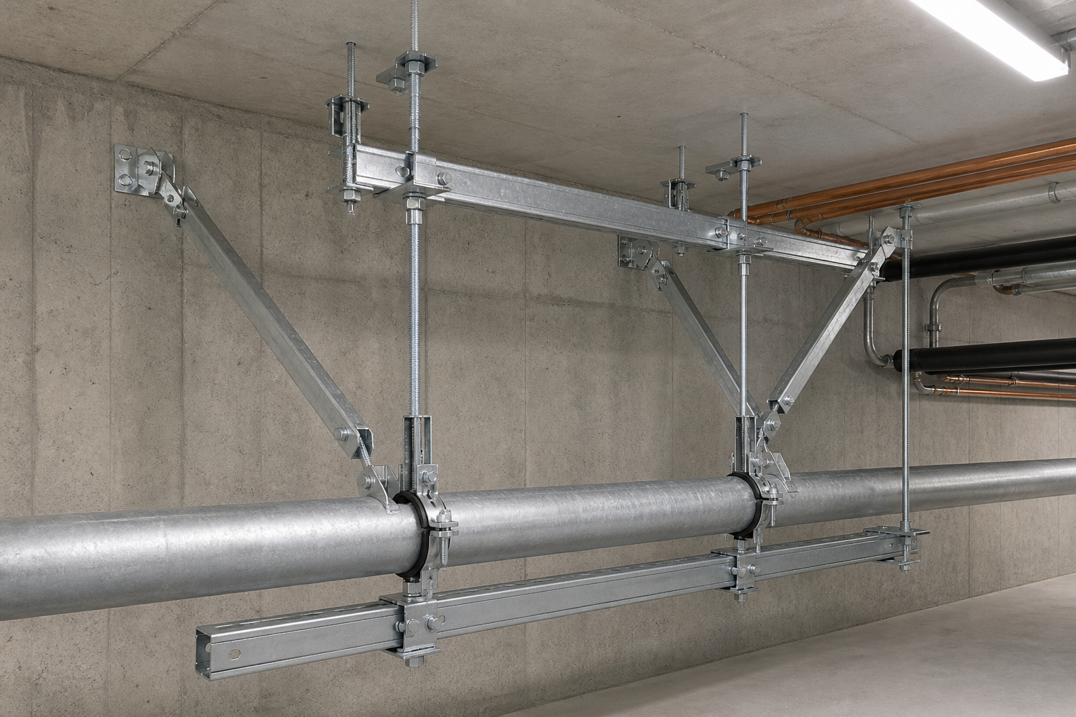
Category-level reference image; confirm the exact member, interface and dimensions for this model against project drawings.
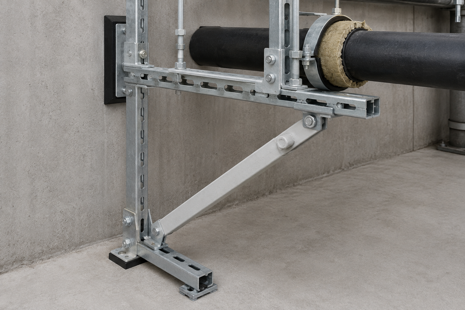
Category-level reference image; confirm the exact member, interface and dimensions for this model against project drawings.
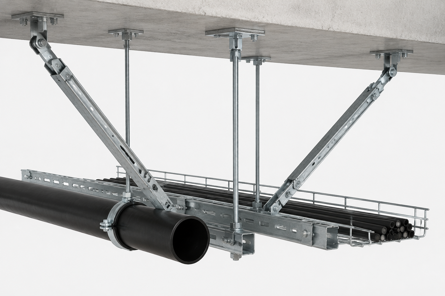
Category-level reference image; confirm the exact member, interface and dimensions for this model against project drawings.
Selection boundary and differentiation notes for Channel Spring-Nut Kit.
Structure, interface and document questions for Channel Spring-Nut Kit (SE-CONNECT-09).
Confirm the product family, interfaces and project conditions against drawings and calculations.
Unlisted dimensions and loads remain project-specific until the engineering package is confirmed.
Yes. Submit project conditions so the applicable documents can be matched.
Channel Spring-Nut Kit (SE-CONNECT-09) should be confirmed against project layout, loads, interfaces and installation conditions.
This page is a category-template migration draft; final values follow the engineering package.
Keep drawings, BOM and site installation interfaces consistent.
Specification sheets, installation nodes, material evidence and BOM interfaces are available by project request.
Provide project boundaries and interface requirements for document matching.
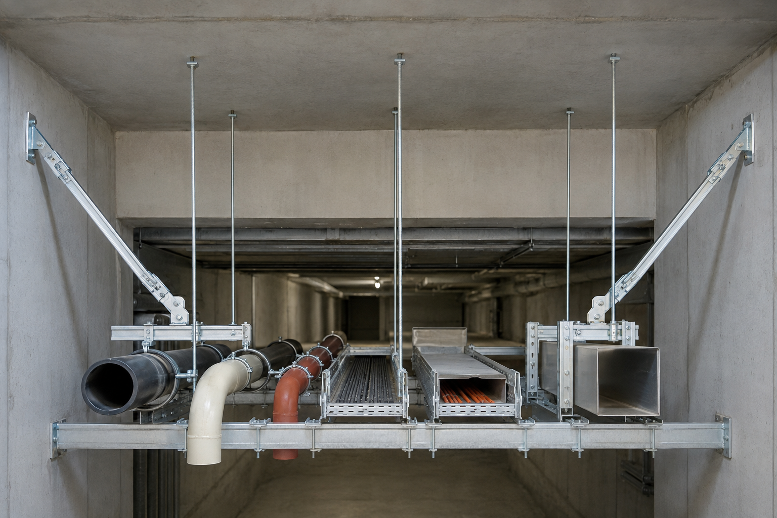
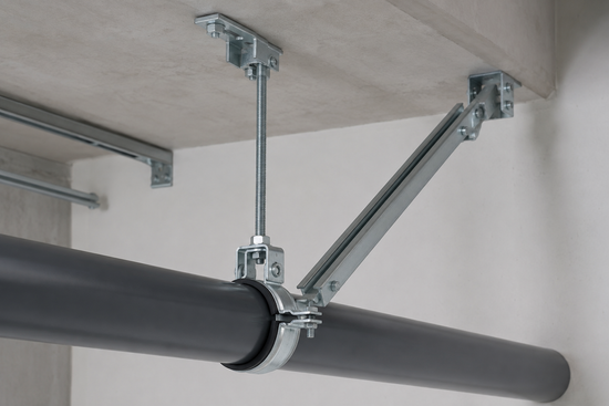
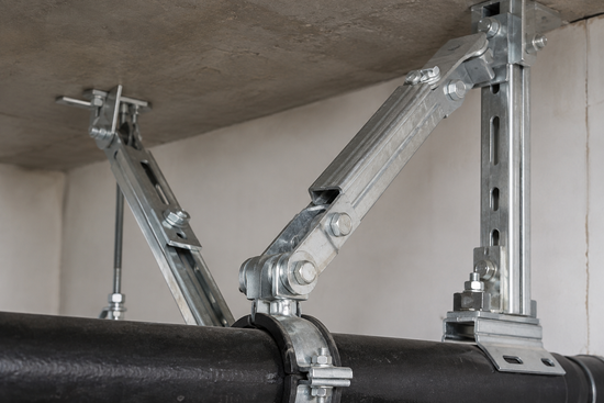
Submit project parameters to match the product configuration and document list.