

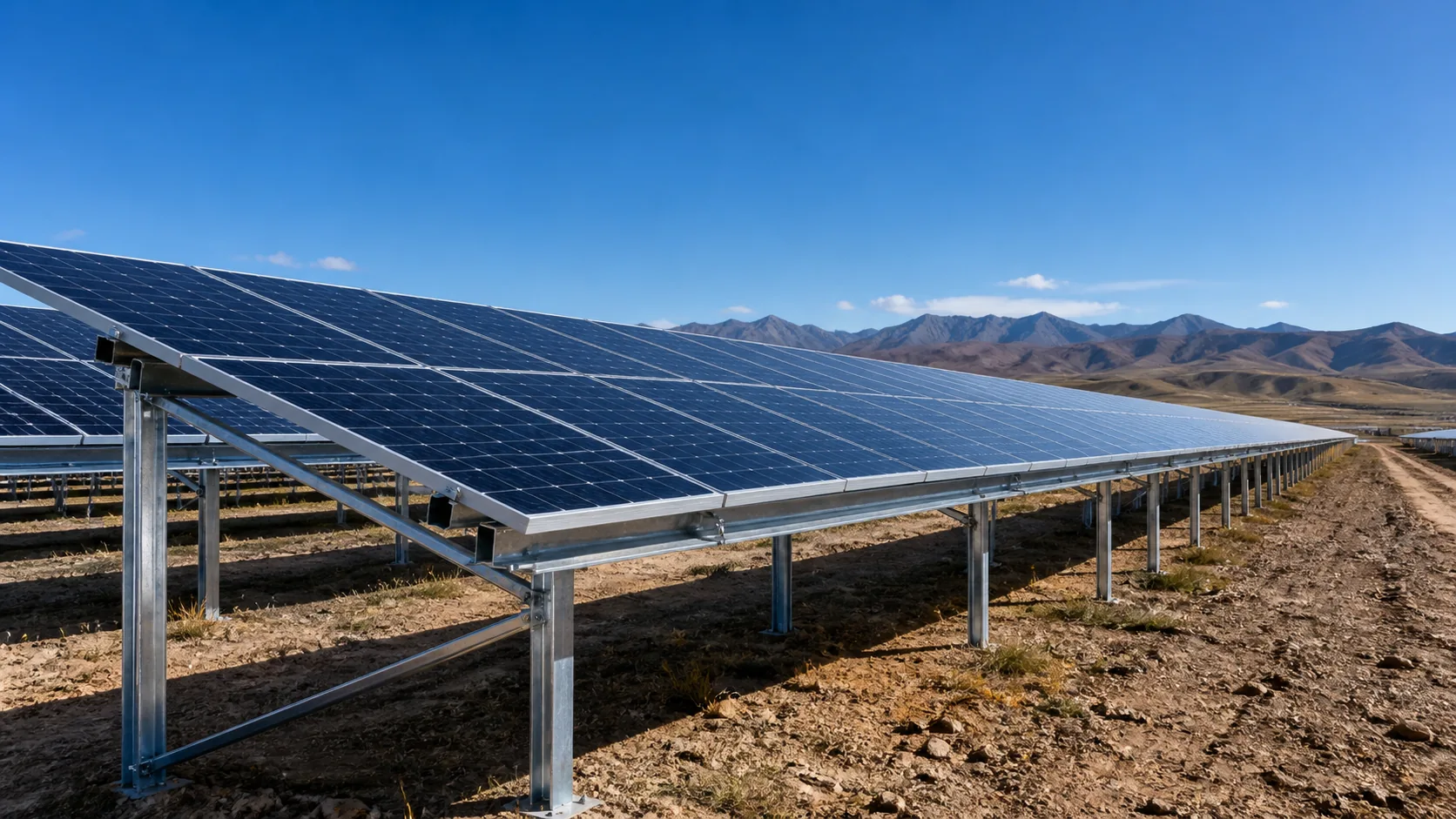
Slope variation
Continuous slope change directly affects post height, module tilt, foundation loads and constructability.
COMPLEX TERRAIN
Slope, aspect, elevation, geology and access jointly change layout and foundation strategy — avoid relying on large-scale grading.
Continuous slope change directly affects post height, module tilt, foundation loads and constructability.
Multi-aspect slopes change array orientation and azimuth — balance generation efficiency with buildability.
Elevation gaps create non-standard grade systems; mounts need height compensation and adaptive nodes.
Soil and rock conditions affect foundation type, anchorage depth and equipment access.
Steep mountain roads and tight turning radii mean transport and lifting must be considered in design.
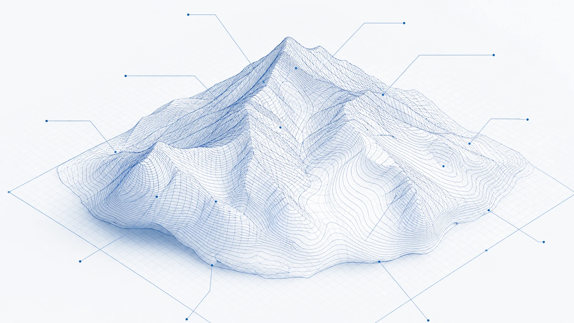
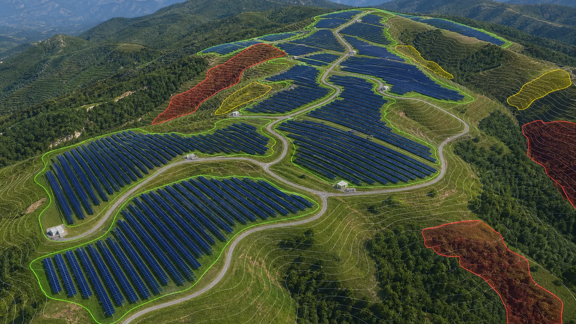
 GIS / TERRAIN MODEL
TERRAIN ADAPTATION
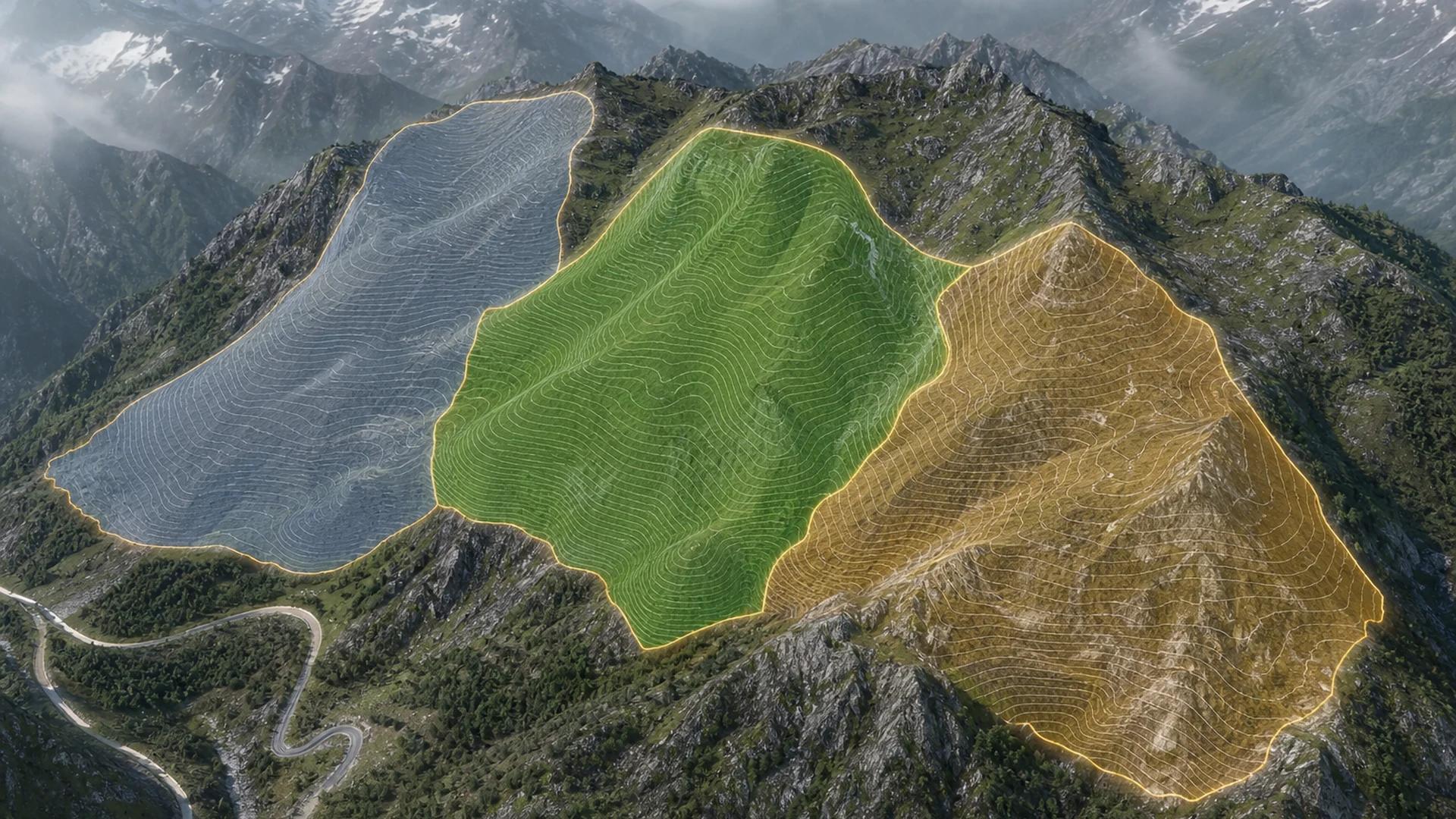
Analyze and zone from real terrain data so array, mount and foundation parameters follow site conditions — not large-scale grading.
DEM / DSM, contours / elevation
Slope / aspect, azimuth analysis
Usable area and zone planning
Height / tilt, foundation conditions
Design principle Reduce unnecessary earthwork, protect original slopes, and adapt through system parameters first.
ARRAY PLANNING
Improve usable area and organization under structure, shading, road and construction constraints.
SYSTEM MATCHING
Foundation type is not a single preset answer — adapt from geotech, loads, slope, equipment access and construction conditions.
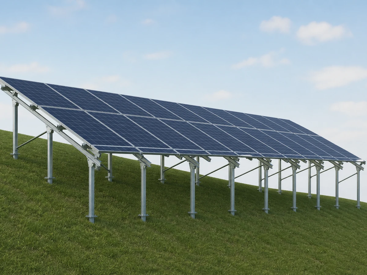 GENTLE SLOPE
Prioritize standard members and regular arrays; use post height to reduce non-standard nodes.
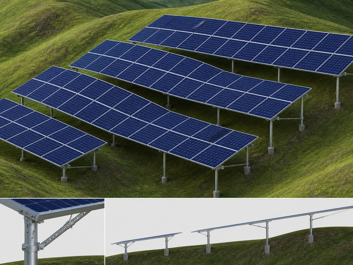 ROLLING TERRAIN
Use variable-height posts, adjustable connections and local compensation to keep array continuity and structural behavior under control.
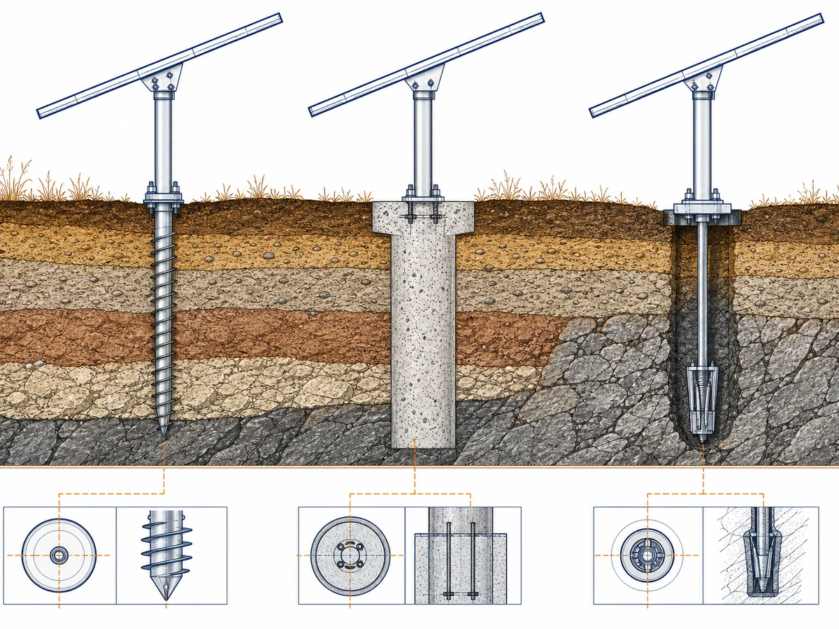 COMPLEX GEOLOGY
Match foundations specially from soil/rock properties, uplift requirements, machinery and transport conditions.
Engineering note: This page explains adaptation logic only. Specific foundation type, embedment and node parameters must follow project geotech, design loads and structural calculations.
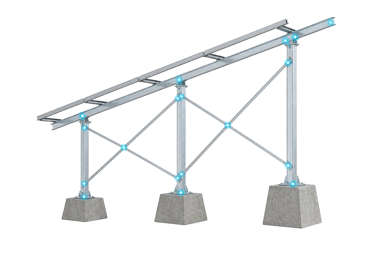
ENGINEERING DETAIL
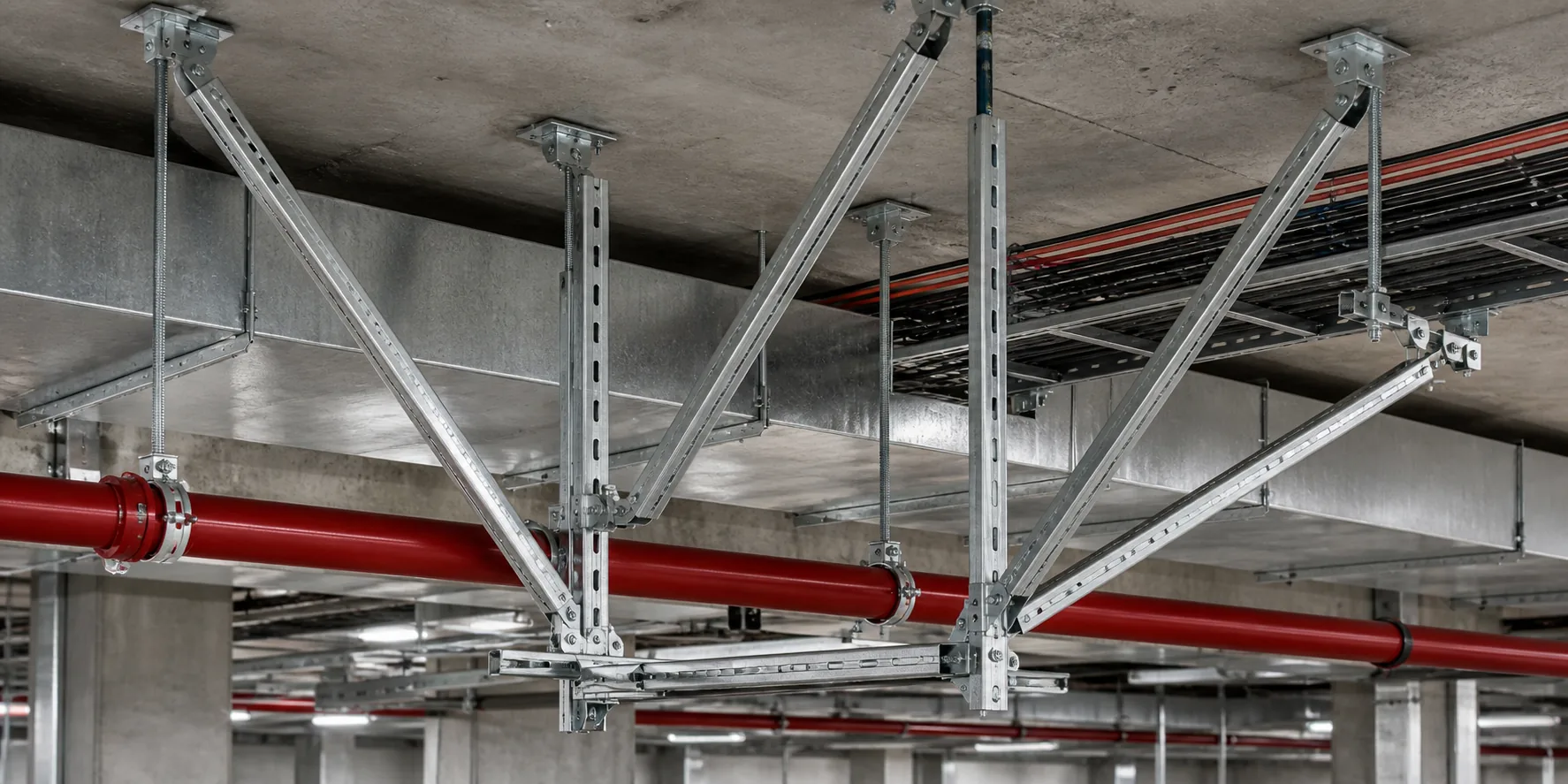
Make terrain adaptation concrete in posts, braces, beam–purlin connections and foundation nodes — not only as a concept.
BUILDABILITY
From design through install, account for mountain transport, manufacturing batches and field constraints together.
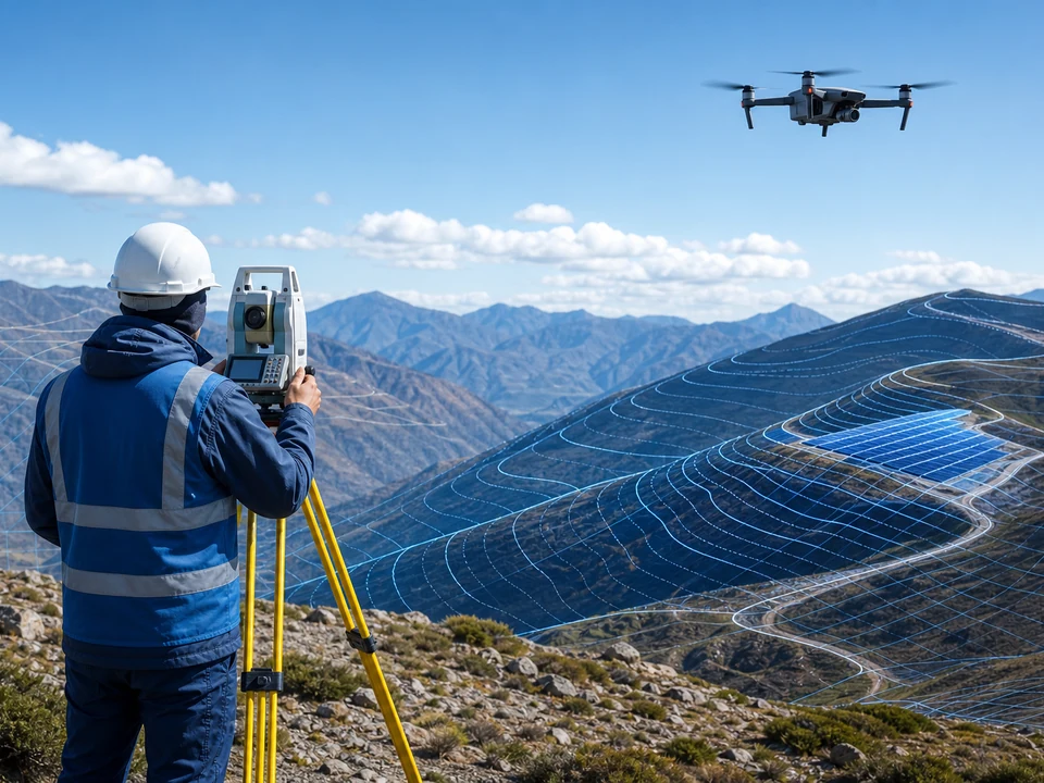 FIELD SURVEY
Verify terrain, geology, roads, drainage and equipment working faces.
Terrain · geology · access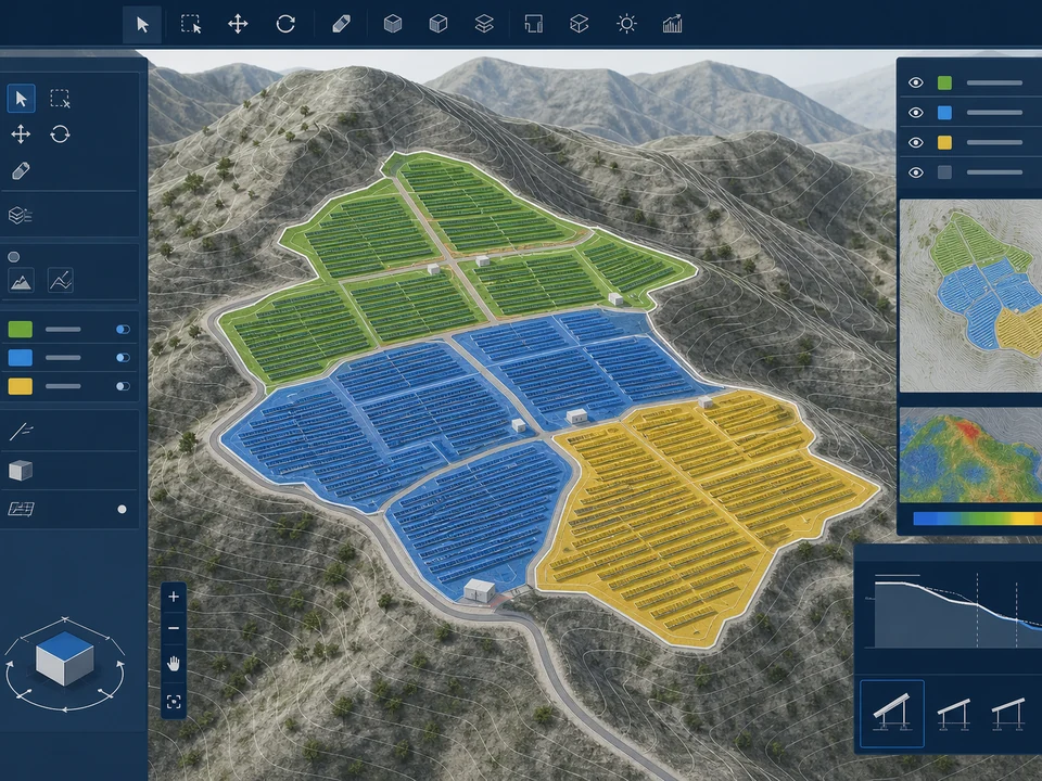 ZONE DESIGN
Establish design zones from slope, aspect and construction conditions.
Zoning · grade · work boundary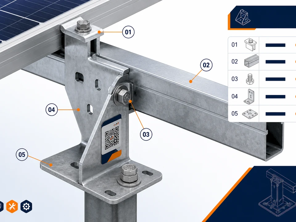 PART CODING
Trace parts, zones and install positions with a consistent coding map.
Coding · BOM · install location BATCH MFG.
Organize production batches and packing lists around the install plan.
Batches · QC · packing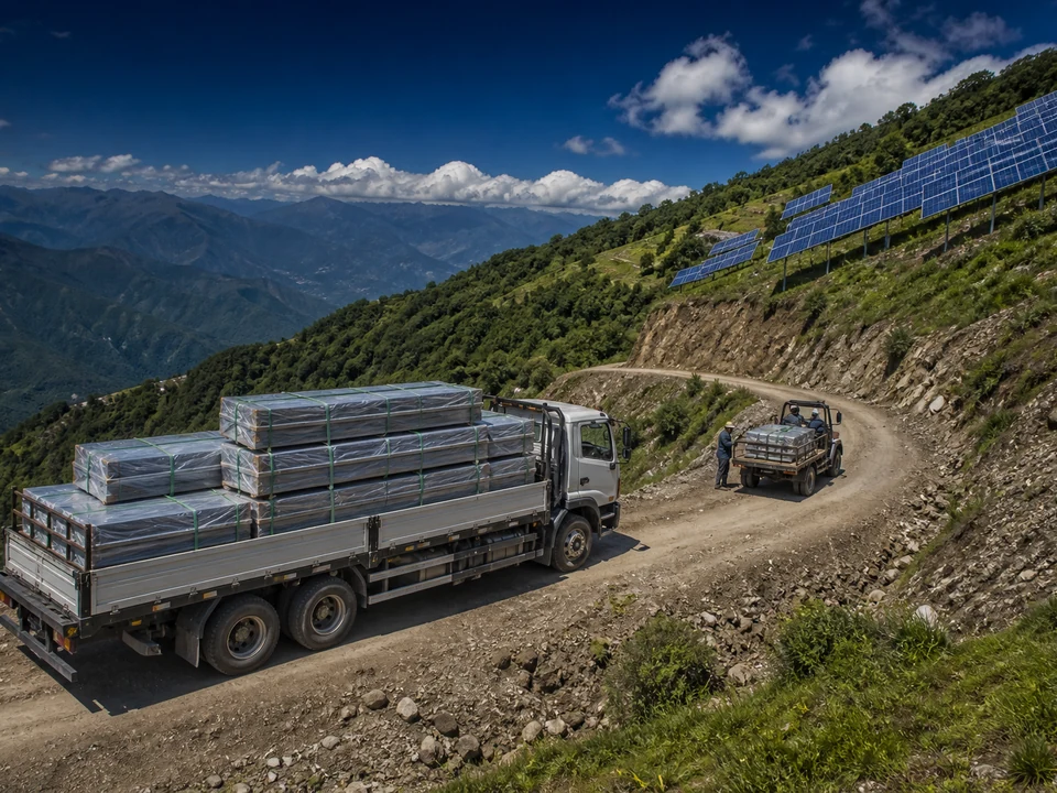 MOUNTAIN LOGISTICS
Account for road width, turning radius and secondary transfer conditions.
Roads · transfer · delivery sequence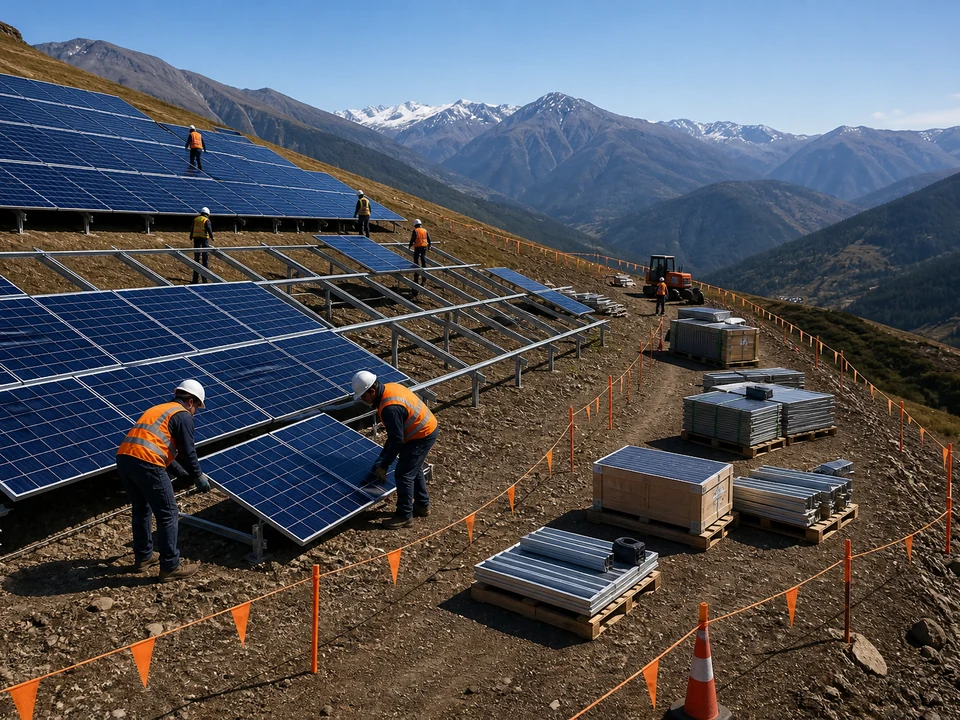 ZONE INSTALL
Advance by code and zone to reduce field identification and rework.
Install · check · handoverBUILDABILITY Consider construction logistics, batch supply and secondary transfers in design so detailing becomes transportable, identifiable and installable on site.
END-TO-END ENGINEERING
Connect terrain inputs, engineering calculation, detailing outputs, manufacturing and zoned delivery into one technical loop.
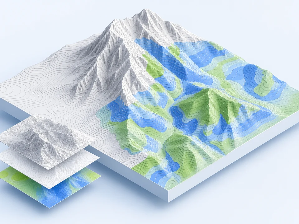
DEM / DSM, slope / aspect, usable-area identification
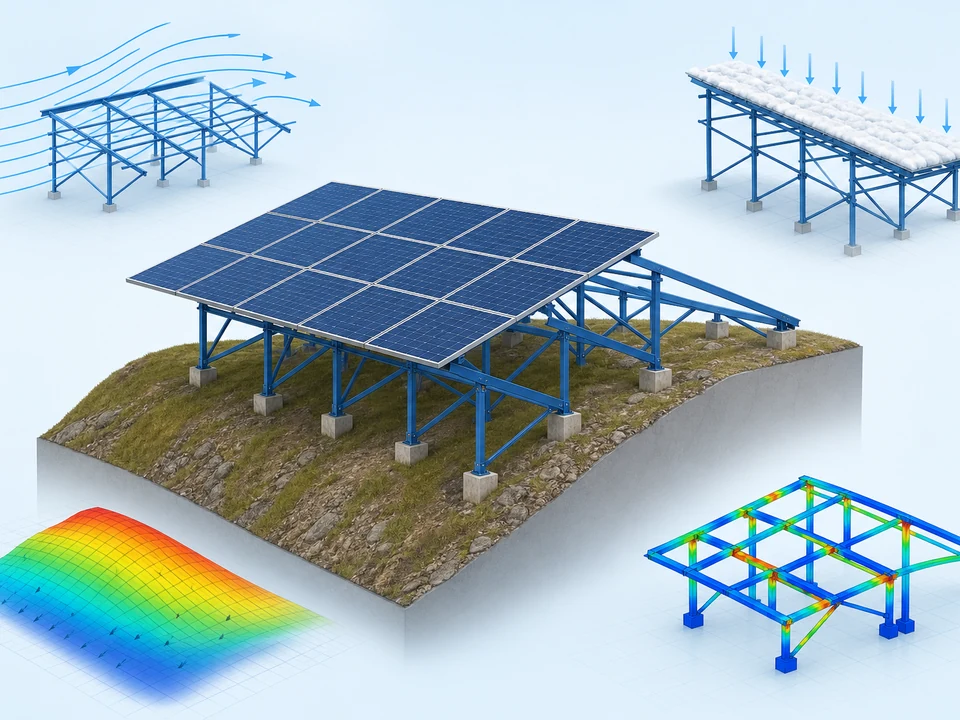
Wind/snow loads, strength / stability, foundation checks
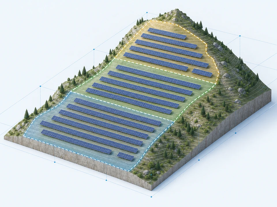
Zoned layout, spacing optimization, elevation control
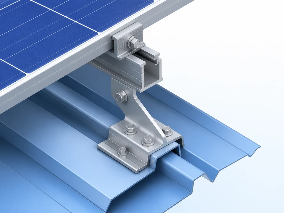
Load checks, detailing, install-process optimization
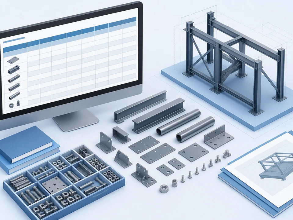
Part lists, specs, coded location mapping
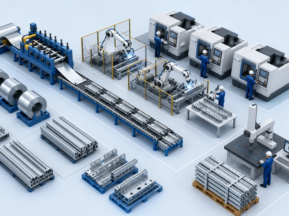
Process control, batch traceability, quality inspection
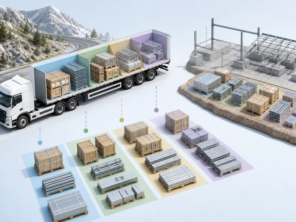
Zoned packing, logistics, site delivery
Submit terrain and project conditions for a professional mounting scheme and quotation guidance.