

PILE-MOUNTED
Pile-mounted elevated fishery-PV Default
Arrays sit above the aquaculture water surface
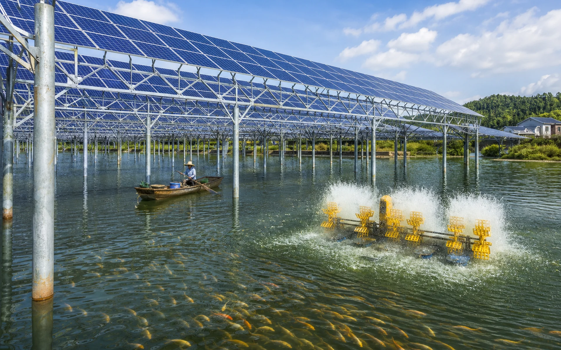
- Pile foundation
- High clearance
- Boat passage
- Feeding
- Aeration
- Harvest
- Shore-side construction
- Maintenance
PROJECT BOUNDARY
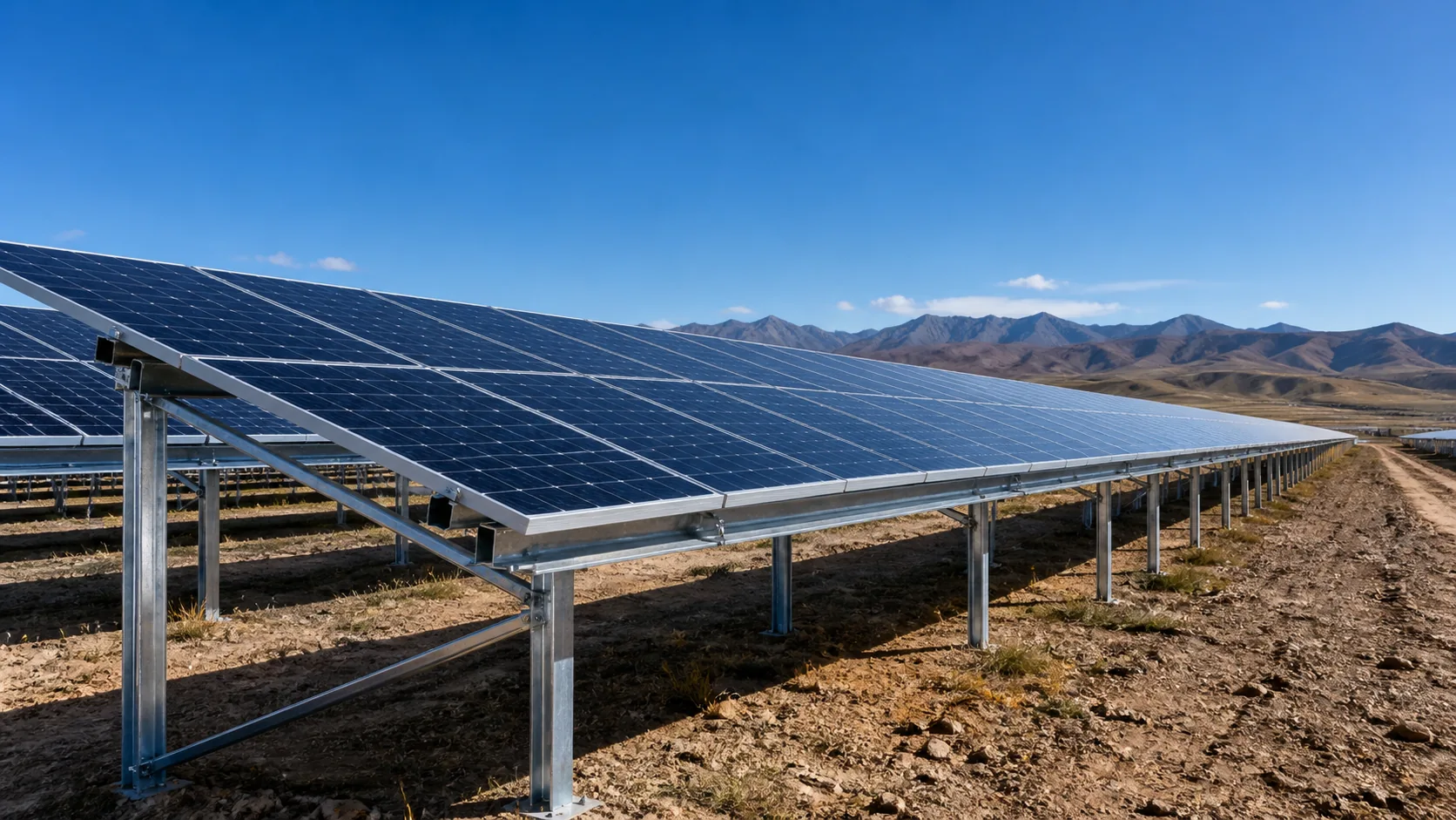
Fishery-PV is not a single mounting form. Identify foundation system, load boundaries and O&M mode first. Floating is comparison-only.
Arrays sit above the aquaculture water surface
Arrays sit directly on floaters
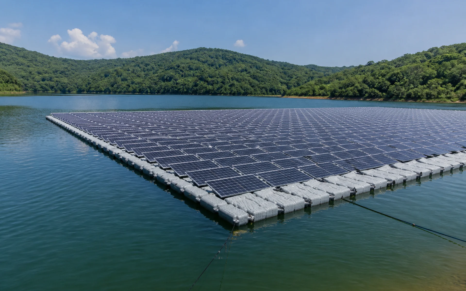
iThe two systems differ significantly in foundation form, load behavior, construction and O&M — decisions must follow water conditions, aquaculture needs and investment boundaries.
PROJECT INPUT MATRIX
Inputs are engineering variables that decide foundation, clearance, layout, durability and O&M paths — not a document checklist.
Depth · normal level · max/min levels · variation
Silt thickness · bearing depth · geotech · pile constructability
Wind pressure · snow · seismic · temperature
Species · boat size · feeding · harvest methods
Module specs · tilt · spacing/span · clearance
Shore roads · over-water work · maintenance routes · electrical layout
SYSTEM SECTION DIAGRAM
Generation, structure, water levels and aquaculture operations must be coordinated in one engineering section.
Spatial relationships are not fixed-size templates. Clearance, spacing, pile depth and work channels must follow project conditions and structural results.
FIVE ENGINEERING CHALLENGES
Silt, bearing stratum and construction method jointly set foundation system and difficulty.
Higher clearance raises wind load, global stability and member stiffness checks.
Materials, coatings and connections need durability design by environment class.
High/normal levels and seasonal change directly affect clearance and O&M safety.
Boats, feeding, aeration, harvest, drainage and maintenance routes must remain usable.
ENGINEERING ANALYSIS
From inputs to deliverables — a verifiable analysis chain, not fixed empirical values replacing project calculations.
Applicable references by scheme boundary: Elevated mounting: project-applicable codes such as NB/T 10115-2018, GB 50009 and GB 50017; floating systems additionally reference floating-specific codes such as NB/T 11814-2025. Confirm code editions in project technical documents.
AQUACULTURE COMPATIBILITY DESIGN
Put array zones, boat channels, work areas and equipment on one plan to reveal operational conflicts.
SYSTEM SOLUTION COMPARISON
No automatic “depth X requires scheme Y” — only engineering judgment directions. Final schemes follow geotech, levels, loads and aquaculture operations.
Note: for early screening only — not project design values or commitments. Final schemes follow project inputs, structural calculation and special design results.
PROJECT DELIVERY PROCESS
A continuous chain from water-condition confirmation to manufacturing and delivery support.
Water, geotech, levels, aquaculture needs and module parameters
Layout strategy, pile vs floating boundary, clearance and channels
Load calc, strength/stability and foundation checks
Node details, BOM, construction drawings and technical files
Fabrication QC, phased supply and site technical support
Submit pond and project conditions for a professional mounting scheme and quotation guidance.