
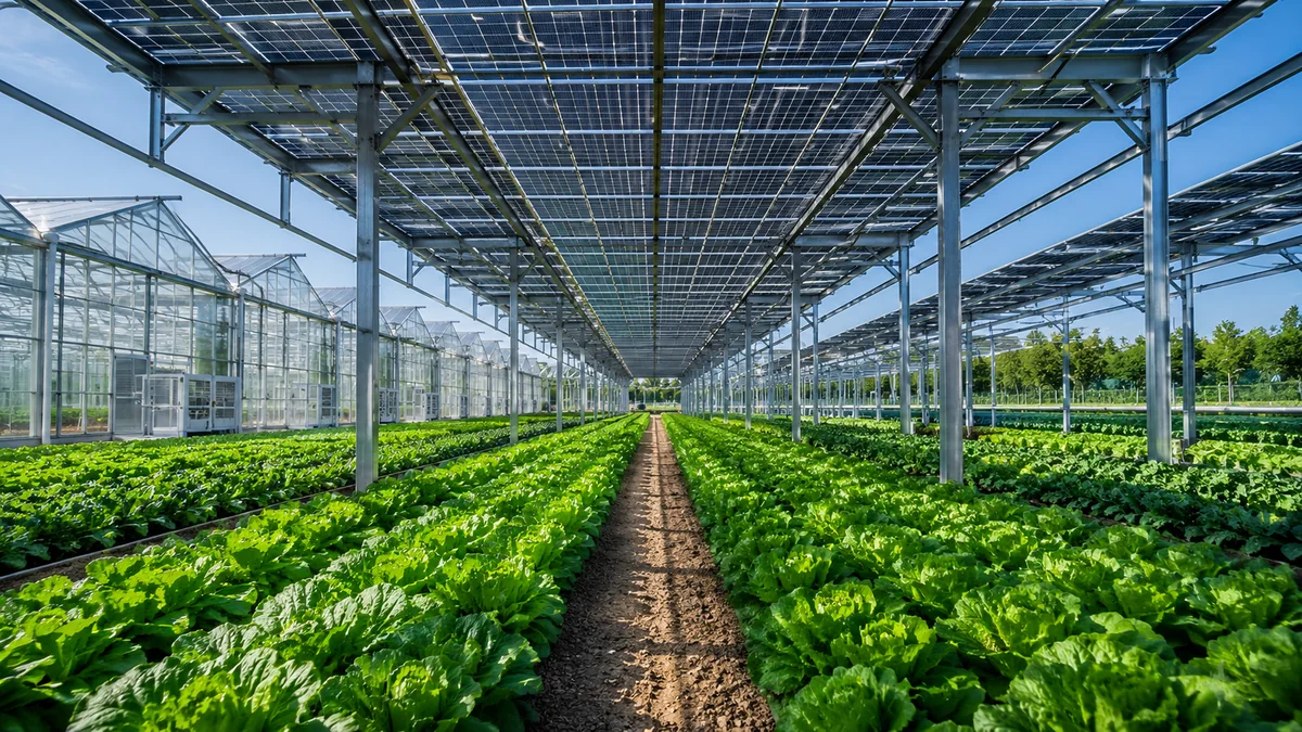
AGRICULTURAL PV SOLUTION

Agricultural PV Solutions

Balance agricultural production space and power generation — systematic design from structure and clearance to light and O&M access.

DUAL PRODUCTION

One System Serving Two Forms of Production

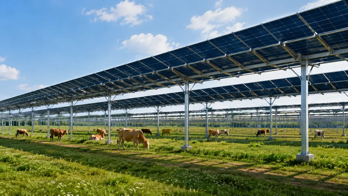
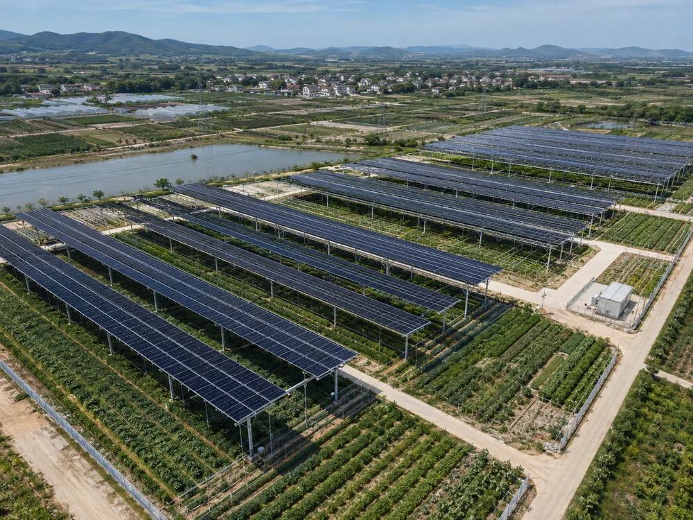
Energy and agriculture share one structural frame: clearance, row spacing, post spacing and drainage must all work.
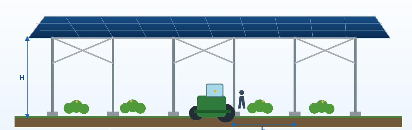
Agricultural PV dual-layer production space engineering illustration
Height H Row Spacing D Column Spacing L Operational Clearance Light Conditions Drainage Layout

MULTI-SCENE ADAPTATION

Adaptation to multiple agricultural scenes

Scene types frame condition discussions; land-use applicability follows local authorities — no yield-increase claims.
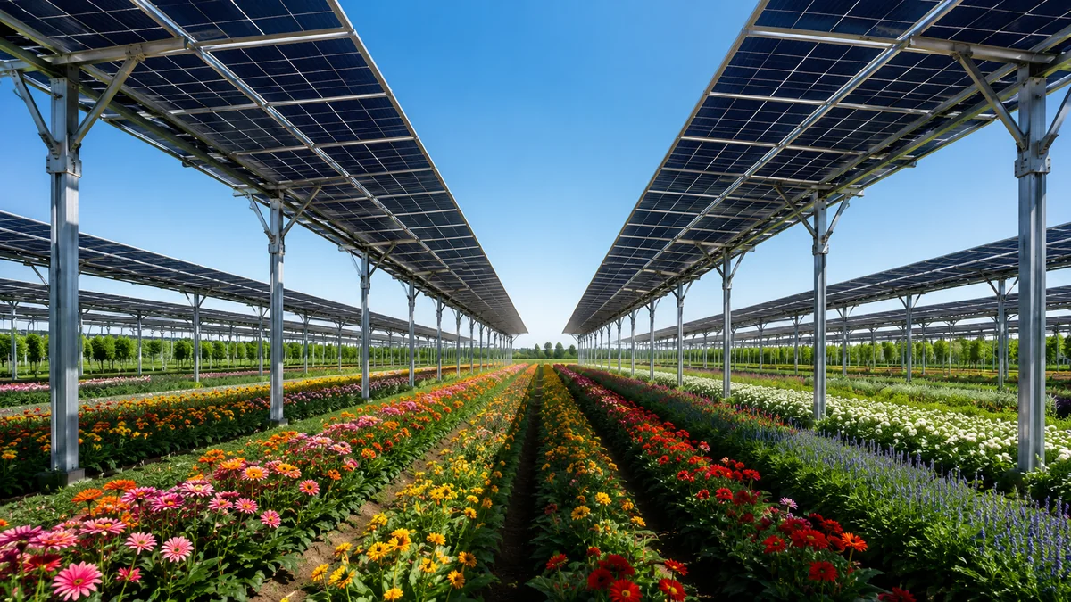
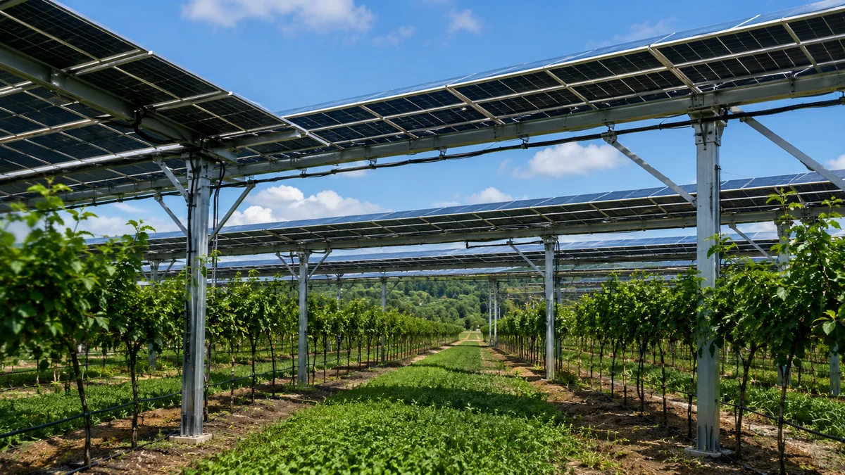
Protected agriculture scenario

Protected Agriculture

  • Greenhouse / polytunnel integration
  • Heat, humidity, ventilation and drainage
  • Daily farm operation space
Horticulture and cash-crop scenario

Horticulture / Cash Crops

  • Flowers, vegetables, medicinal plants
  • Optimize shading, ventilation and work space
  • Balance quality and production needs
Orchard and fruit tree scenario

Orchard / Fruit Trees

  • Orchards, tea gardens, vineyards
  • Adapt to plant height and row spacing
  • Enable pruning and harvest access
Large-scale farming and breeding scenario

Large-scale Farming & Breeding

  • Pastures and mixed agriculture
  • Large spans, ventilation and drainage
  • Reserve machinery and management routes

Specific construction conditions and land suitability are subject to requirements of local natural resources, agricultural/rural, and energy authorities.

DIMENSION LOGIC

Every Dimension Derived from Agricultural Production Conditions

All parameters require structural calculation and engineering detailing based on actual project conditions.
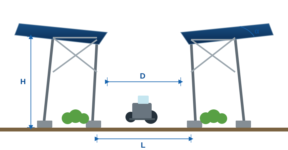
Agricultural PV mounting height, row spacing, and column spacing engineering section
H Clearance Height Determined by crop height, machinery height, and maintenance access
D Inter-Row Clearance Balance sunlight, machinery access, and working space
L Column Spacing Matched to planting module and structural calculation requirements
α Module Tilt Angle Determined by irradiance, drainage, generation, and shading conditions
F Foundation Type Selected based on geology, water table, loads, and construction conditions

LIGHT & OPERATIONS

Generation Efficiency and Crop Lighting — Not an Either-Or Choice

Light scenarios are conceptual design illustrations; actual array spacing, shadow extent, and effective crop lighting must be based on site irradiance, terrain, and array model calculations.
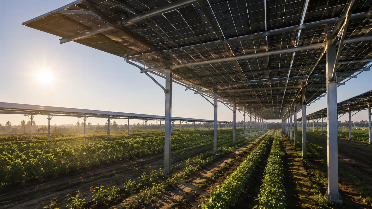
09:00 Morning Period
Morning light and shadow illustration

Crop Light Window

Optimize effective crop lighting windows and reduce adverse shading impacts.
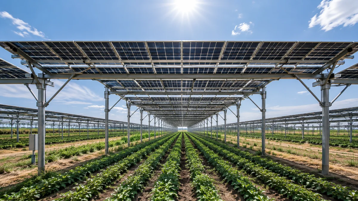
12:00 Midday Period
Midday light and shadow illustration

PV Generation

Coordinate generation efficiency, shading, and structural safety during high-irradiance periods.
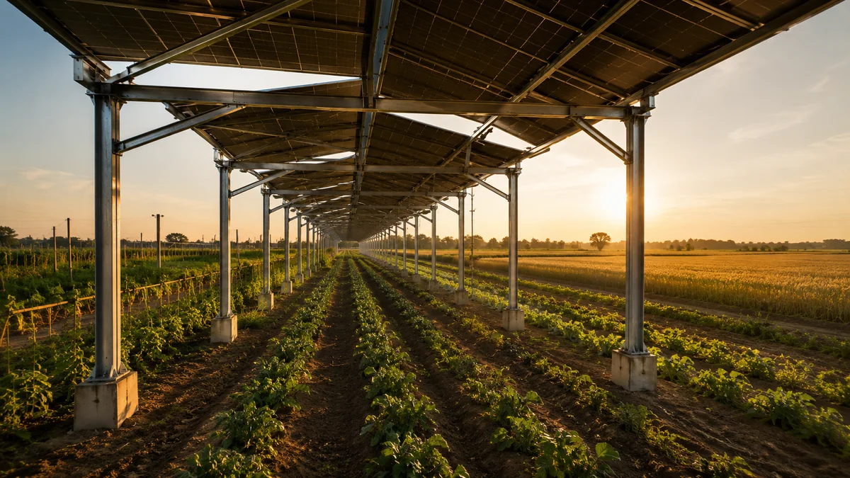
15:00 Afternoon Period
Afternoon light and shadow illustration

Machine Corridor

Reserve farm machinery corridors and clearance for operations and maintenance.

MOUNTING SYSTEM COMPONENTS

Mounting System Components

Break down posts, beams, purlins and connections so clearance requirements can be checked against the structure.
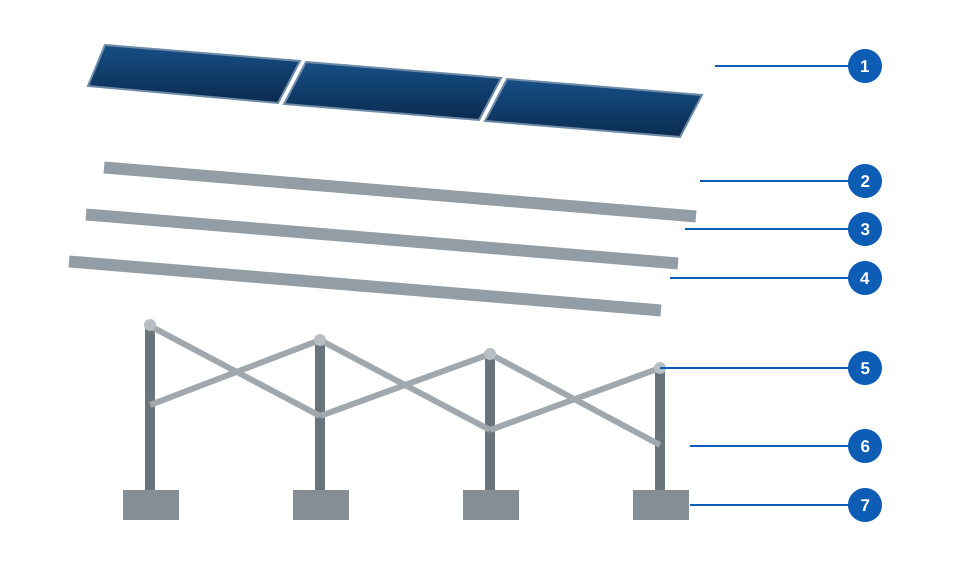
Agricultural PV mounting system exploded structure illustration
  1. Module Clamps Secure modules and meet installation adjustment requirements
  2. Purlin System Support modules and transfer loads to main beams
  3. Main Beam System Carry primary loads and form the main structural system
  4. Post System Provide vertical support and maintain agricultural operational clearance
  5. Brace System Improve lateral stiffness and overall structural stability
  6. Connection Details Enable standardized assembly, installation, and maintenance
  7. Foundation System Selected based on geology, water table, and load conditions

ENGINEERING PROCESS

Engineering Process from Agricultural Conditions to Mounting Delivery

Write farm operation boundaries into structural inputs, then move into calculation, detailing, manufacture and install.

Current phase focus Confirm agricultural production conditions and engineering boundaries to avoid structural parameter rework later.

DURABILITY & SAFETY

Safety & Durability Control in Agricultural Environments

Risk checklist for intake verification — not a substitute for specialty calculations.
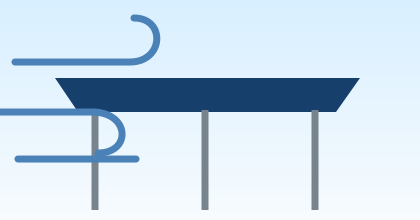
Wind load risk illustration WIND Wind Load

Elevated structure wind load design to reduce array risk.
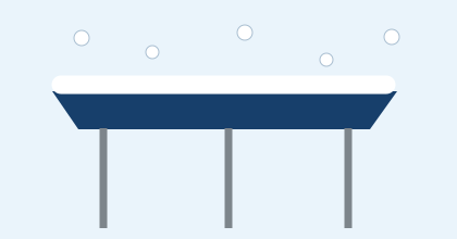
Snow load risk illustration SNOW Snow Load

Structural capacity verification for safe snow loading conditions.

Corrosion environment risk illustration CORROSION Corrosion Resistance

Corrosion protection systems selected for agricultural humidity and environment.
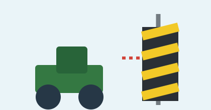
Farm machinery impact risk illustration IMPACT Impact Protection

Equipment and structure protection to reduce farm machinery collision risk.

Drainage organization risk illustration DRAINAGE Drainage Management

Organized centralized drainage to reduce erosion and ponding risk.

Cable safety risk illustration CABLE Cable Safety

Proper routing and protection, avoiding agricultural operation zones.

ENGINEERING DELIVERY

From Agricultural Conditions to a Constructible Mounting System

Project input → engineering detailing → delivery services in a verifiable loop.
PROJECT INPUT Project input
Project input
  • Site and crop condition survey
  • Machinery and operation requirements
  • Climate and geological conditions
  • Module parameters and project goals
ENGINEERING Engineering detailing
Engineering detailing
  • Light and array scheme optimization
  • Mounting structure design and checks
  • Foundation and node detailing
  • Drainage and electrical coordination
DELIVERY Delivery Services
Production delivery
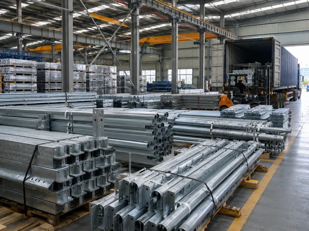
  • Component manufacture and QC
  • Logistics and on-site delivery
  • Installation technical support
  • Acceptance and after-sales support

Define a constructible mounting system from agricultural conditions

Submit farming and site conditions for a professional mounting scheme and quotation guidance.