
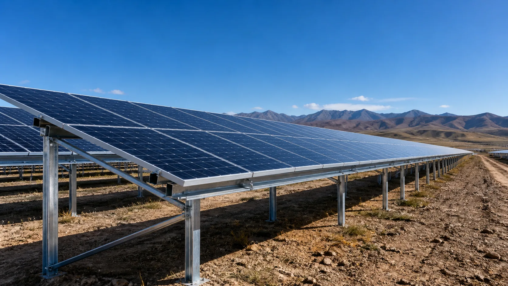
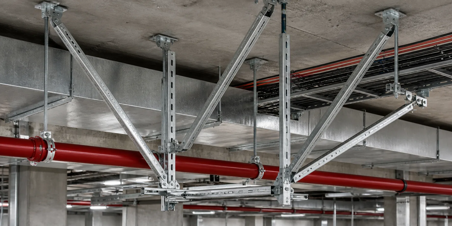
COMMERCIAL & INDUSTRIAL ROOFTOP PV

C&I Rooftop PV Solutions

For industrial plants, parks and commercial buildings — design arrays, mounts and fixing interfaces from roof conditions.

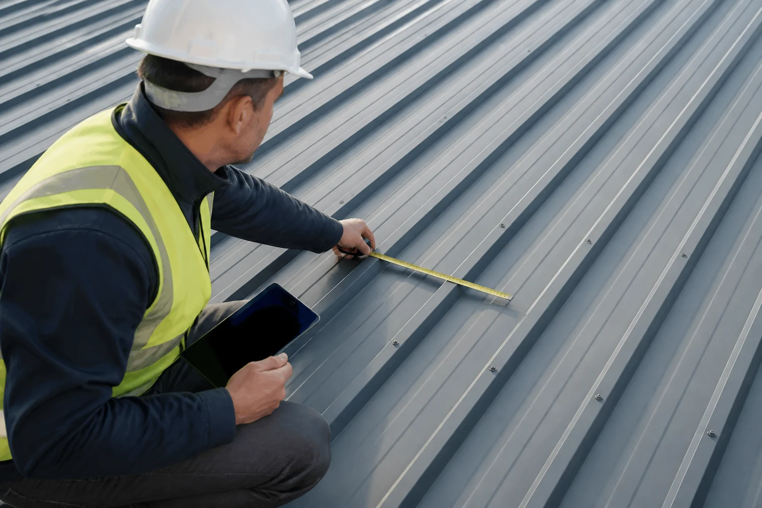
ROOF CONDITION ASSESSMENT

System design starting from roof conditions

Confirm building conditions before array, mounting and fixings. Roof type, structural capacity, local wind climate and existing waterproofing all set the design boundary.
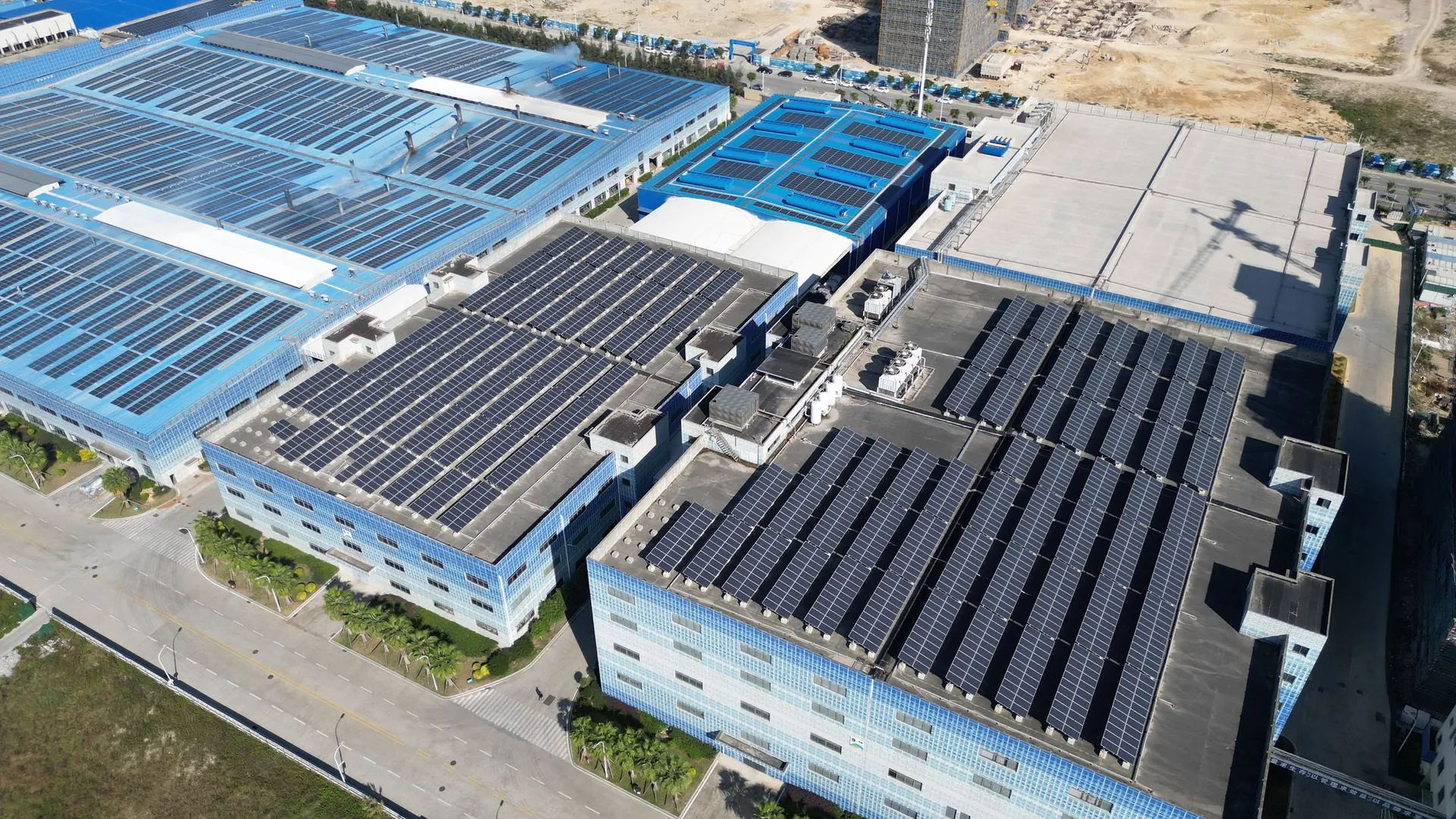
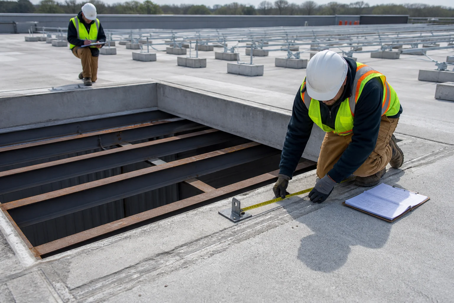
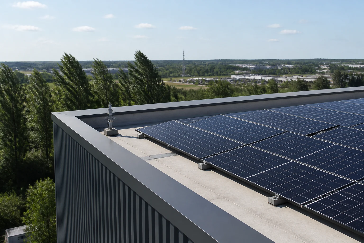
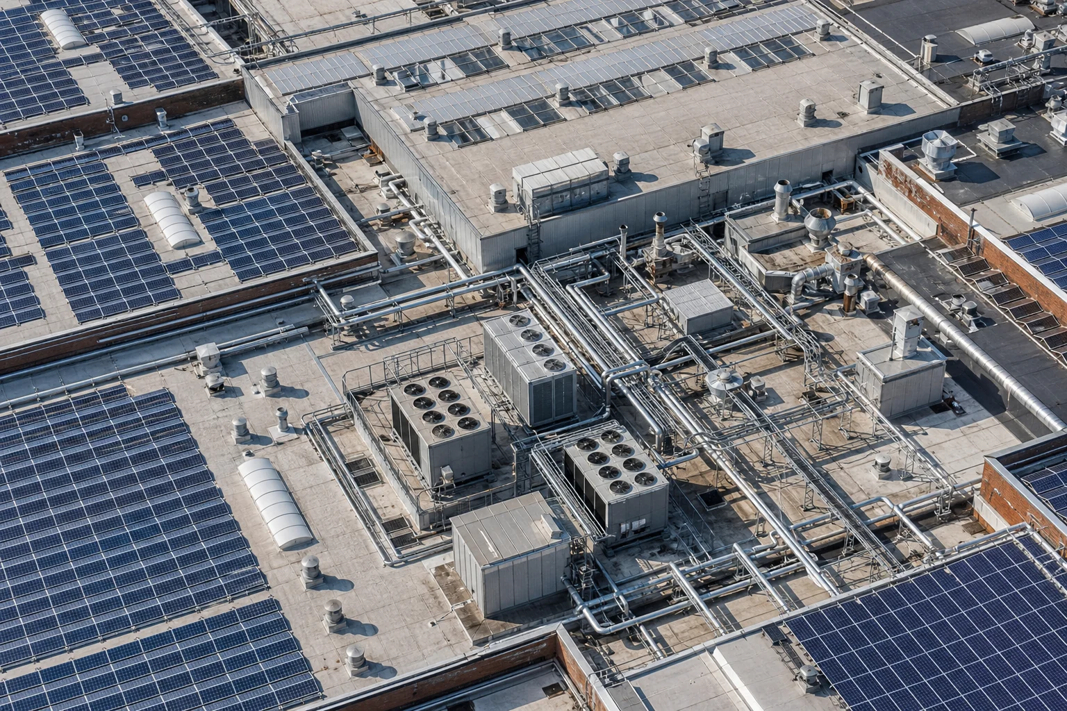
Industrial rooftop PV site photo
Assess first, then select Building conditions are the first input for rooftop PV design
Roof type assessment scene
01 Roof type Identify roof construction, profile and substrate to set mounting fit and fixing boundaries.
Structural load review scene
02 Structural loads Use existing structural data and checks to control added dead load and construction-stage effects.
Wind load check scene
03 Wind loads Check wind loads and design nodes from site location, building height and roof zones.
Waterproofing review scene
04 Waterproofing Review membrane type and existing details so structural fixings do not become leakage risks.

ROOF TYPE ADAPTATION

Adaptation across multiple roof types

One node does not cover every roof — choose fixing methods and load paths that match the building construction.
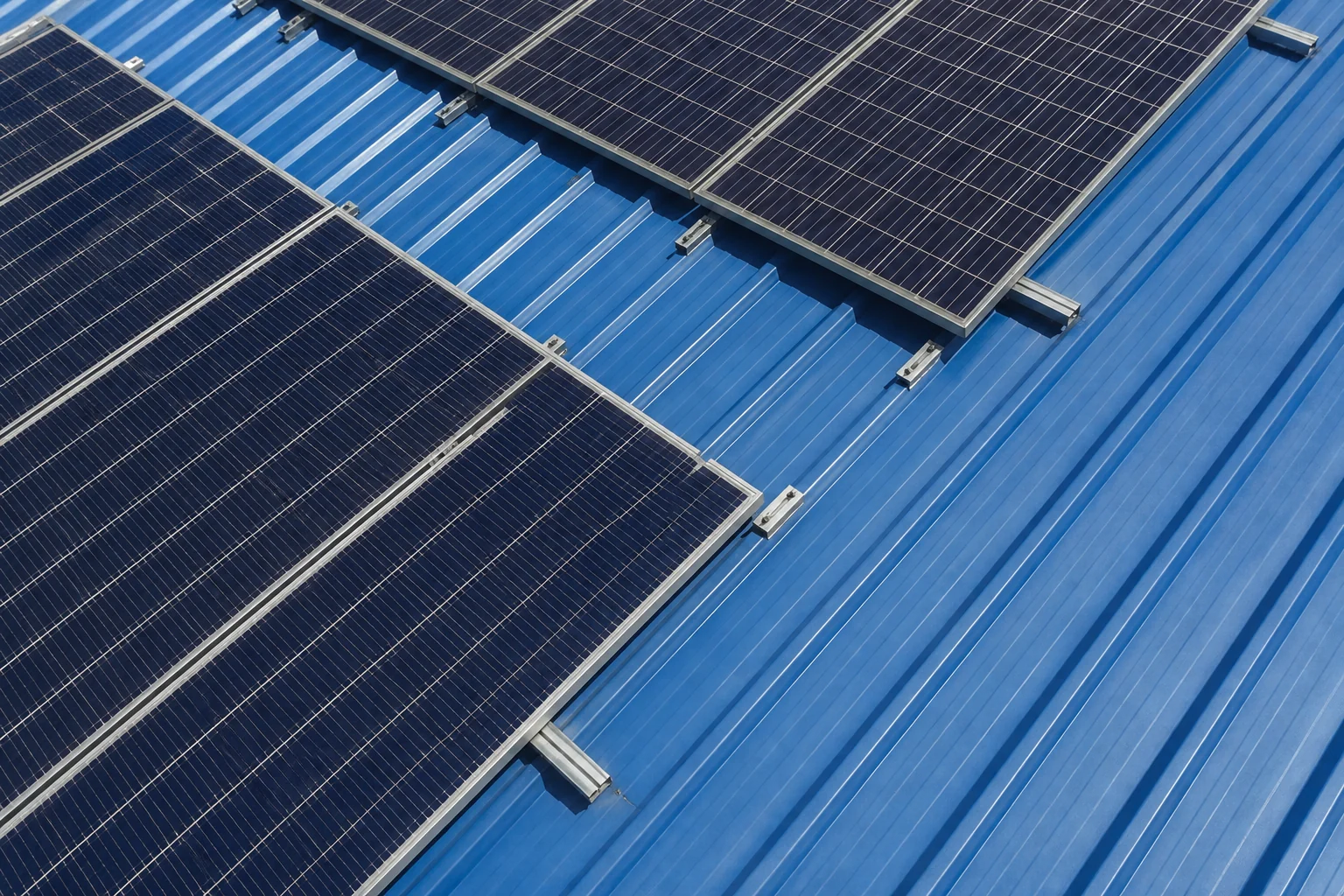
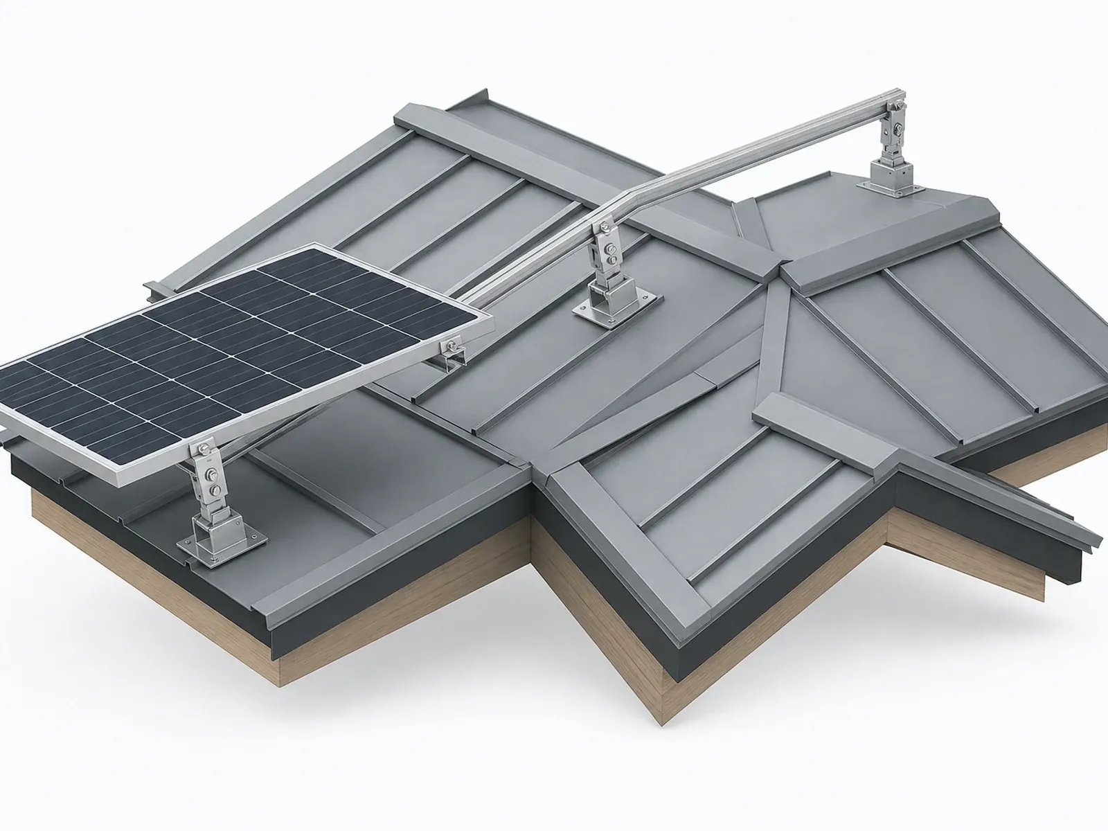
Metal roof scenario METAL ROOF
01 / METAL

Metal / standing-seam roofs

Match clamps to profile, seam type and purlin conditions; avoid unnecessary roof penetrations.

View installation strategy
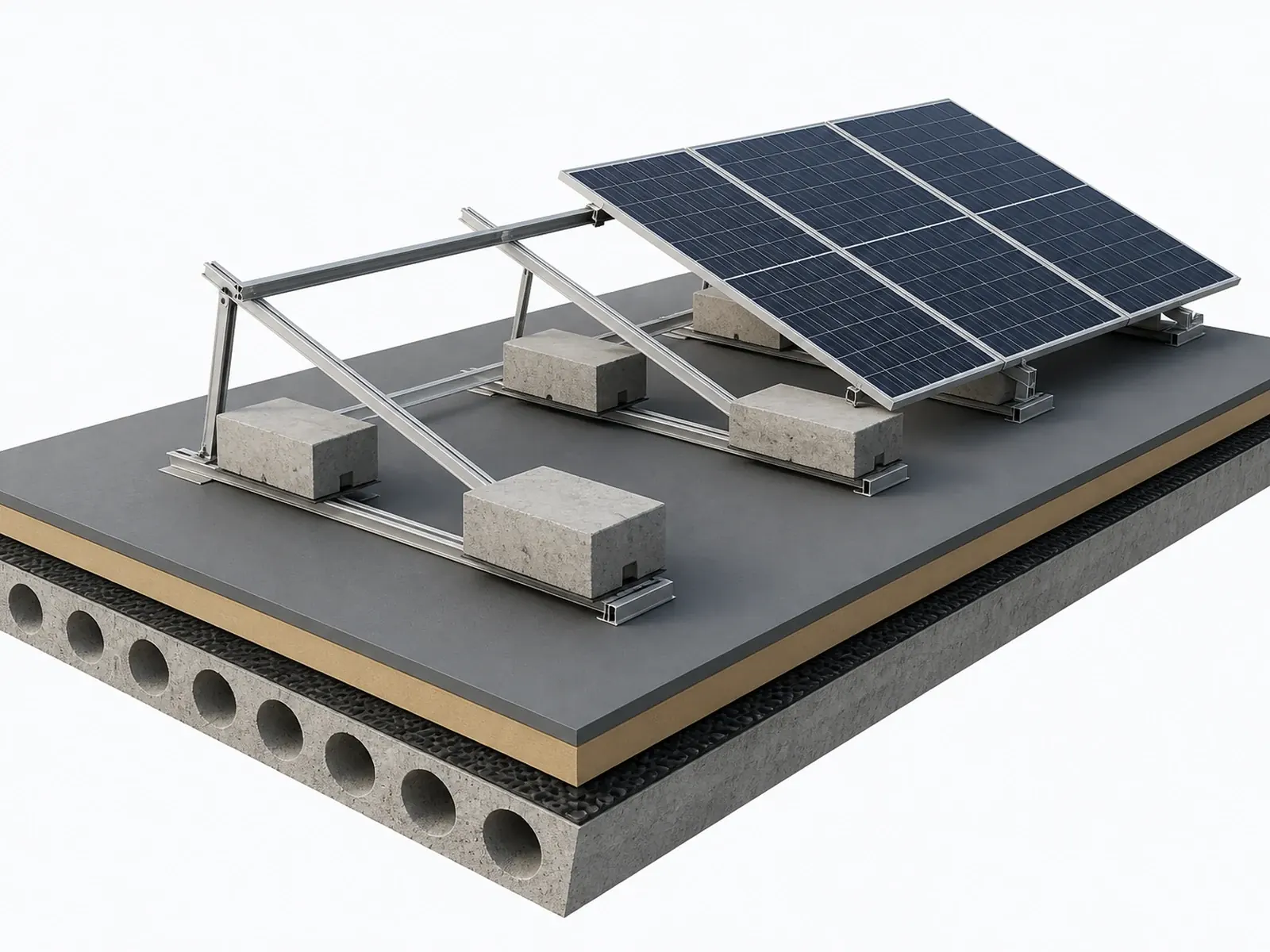
Concrete flat roof scenario CONCRETE ROOF
02 / CONCRETE

Concrete flat roofs

Choose ballast or mechanical fixing from structural capacity, waterproofing and array layout.

View installation strategy
Membrane roof scenario MEMBRANE ROOF
03 / MEMBRANE

Flexible membrane roofs

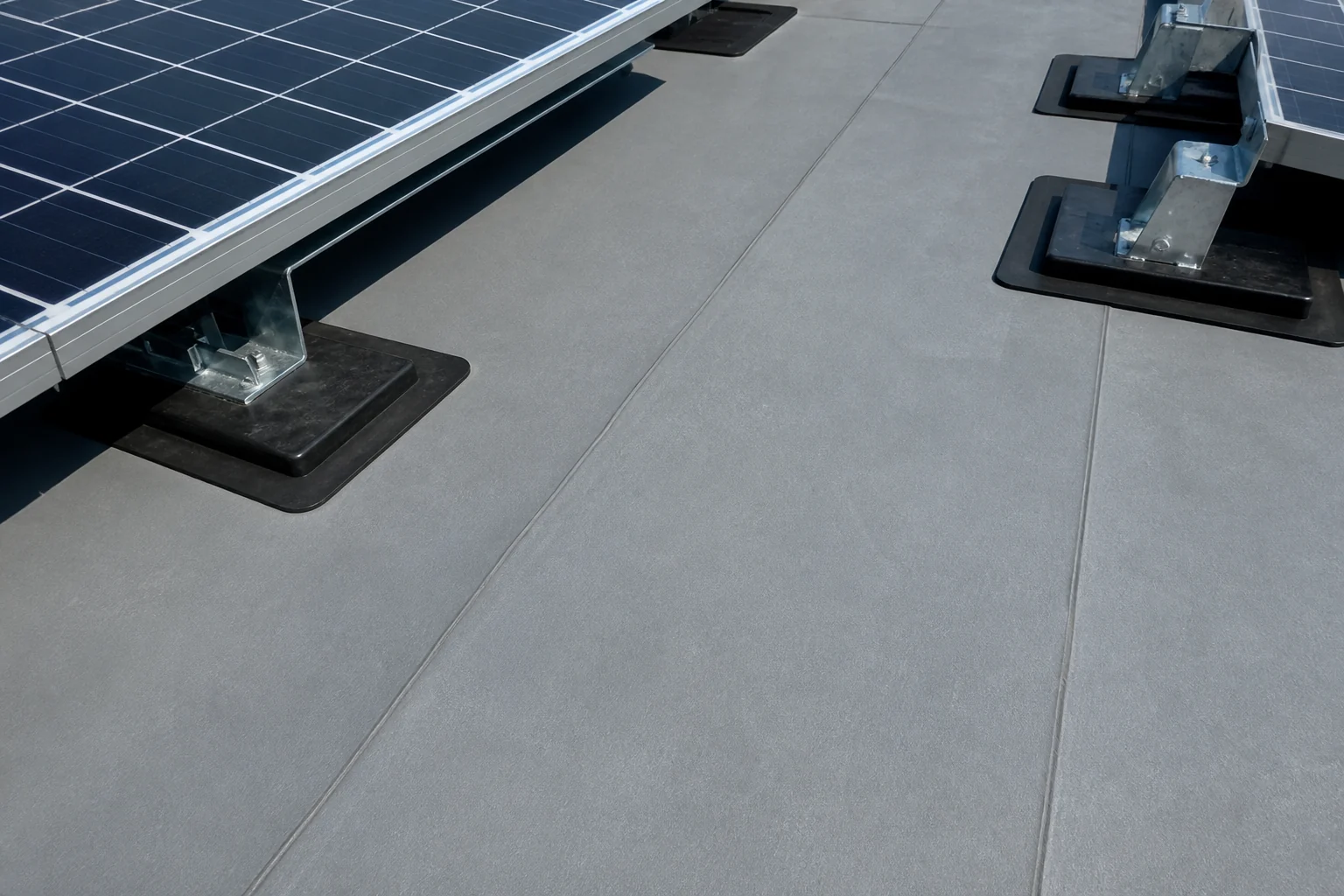
Protect the membrane, control local loads and wind uplift; keep fixings coordinated with the existing roof system.

View installation strategy
Complex industrial roof scenario COMPLEX ROOF
04 / COMPLEX

Complex industrial roofs

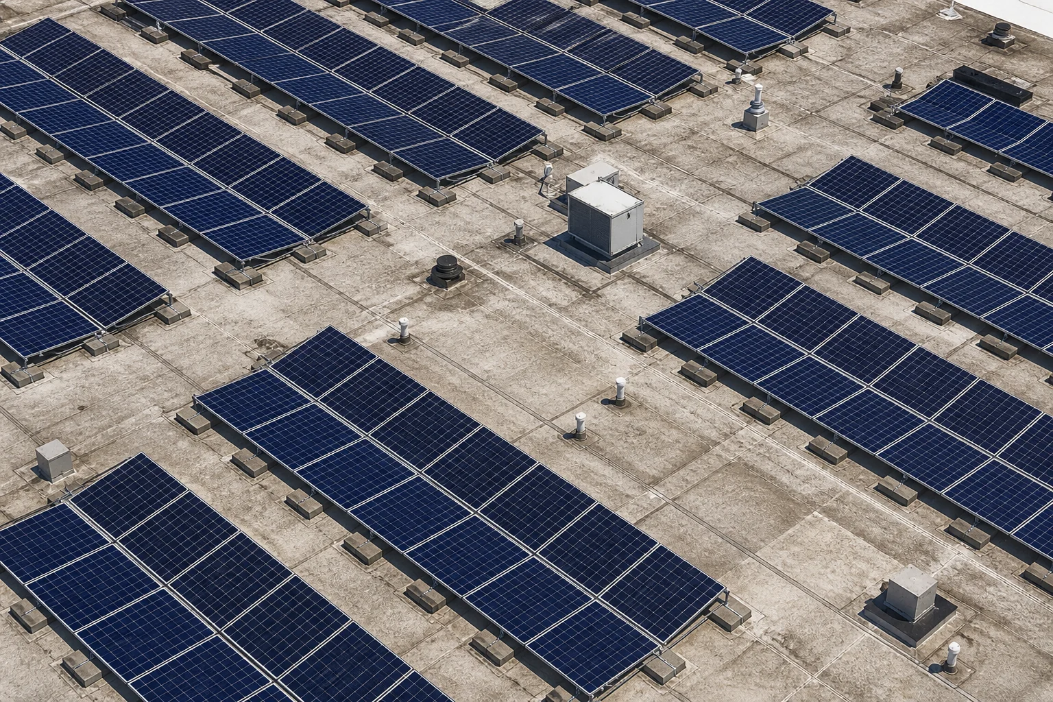
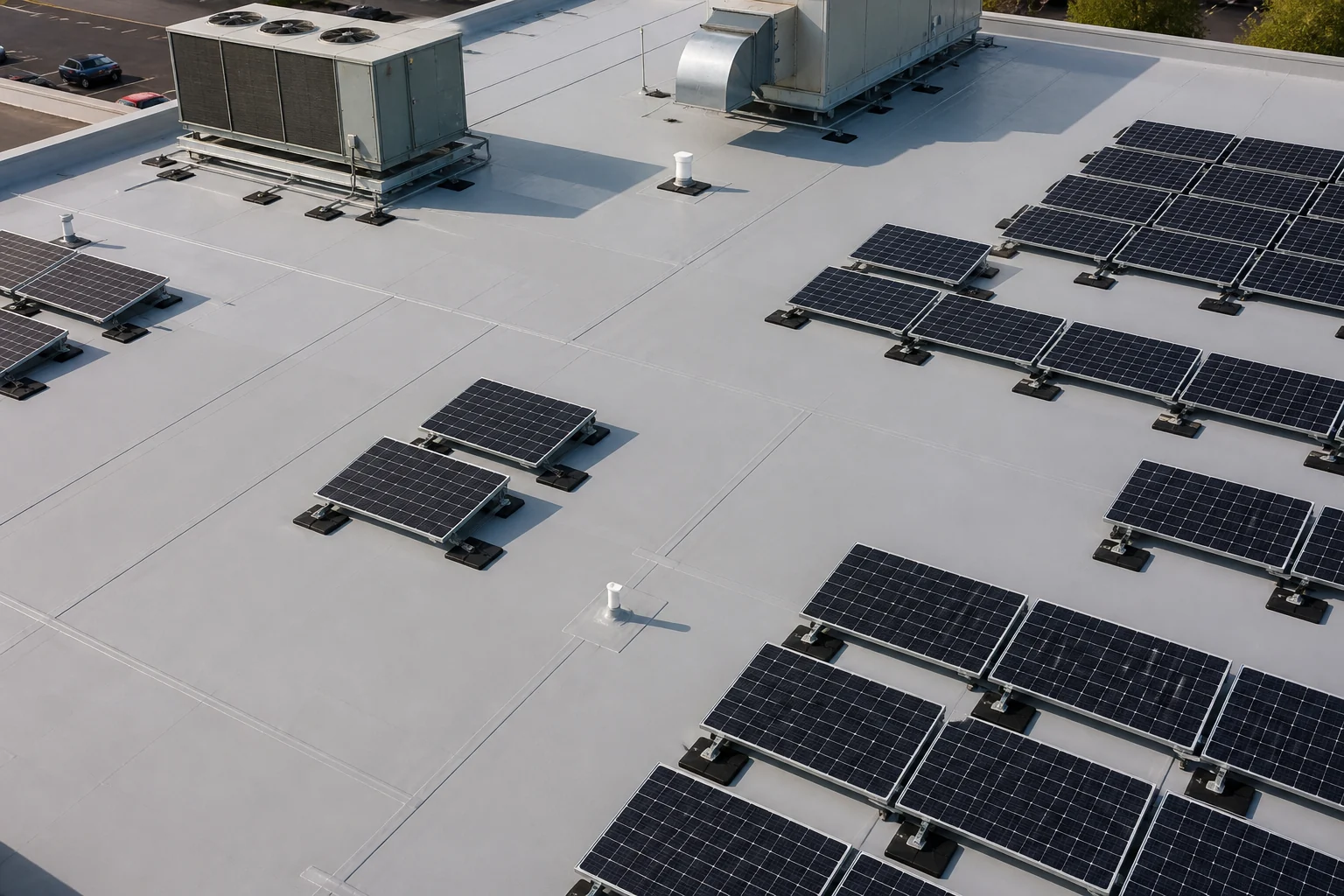
Resolve conflicts from stepped roofs, dense equipment, skylights and existing services with zoned layout and custom nodes.

View engineering layout

SYSTEM ENGINEERING LAYOUT

Rooftop PV system engineering layout

Coordinate arrays, access, fire routes, electrical paths and O&M constraints on one engineering plan — not just fill the roof with modules.
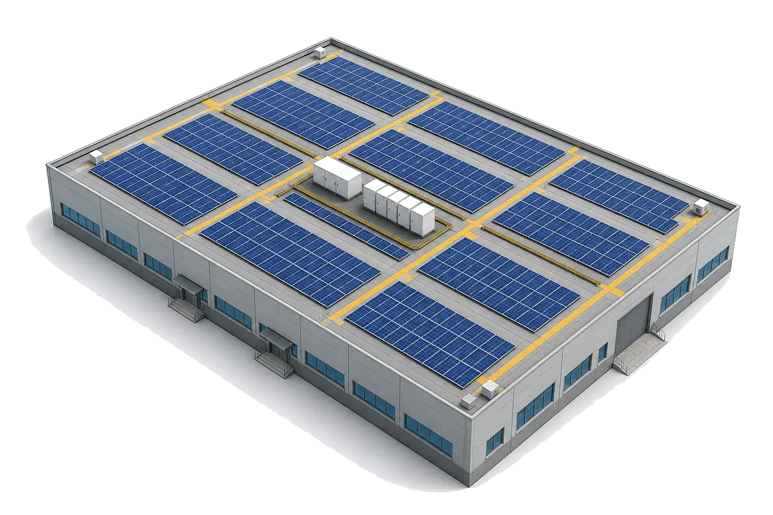
C&I rooftop PV engineering layout illustration

Engineering illustration — final layout follows project detailing Select side elements to locate matching nodes on the photo

STRUCTURAL RELIABILITY

Safety and structural reliability

Reliability comes from a closed engineering chain: structural inputs, load calculation, node detailing, corrosion protection and site acceptance.

01

Structural review

Identify structural system and capacity boundary

02

Wind load calculation

Zone-check system uplift resistance

03

Node design

Define connections, load transfer and detailing

04

Corrosion scheme

Match materials to environmental exposure

05

Install acceptance

Key process checks and quality closeout

Connection nodes Clamps / rails / fasteners
Anchorage nodes Base plates / posts / anchors
Wind uplift resistanceLoad controlConnection reliabilityLong-term corrosion resistance

INSTALLATION STRATEGY

Installation strategies that protect the roof

“No roof damage” is not an absolute promise for every roof. Choose nodes that balance structural safety, waterproof continuity and constructability for the actual roof build-up.
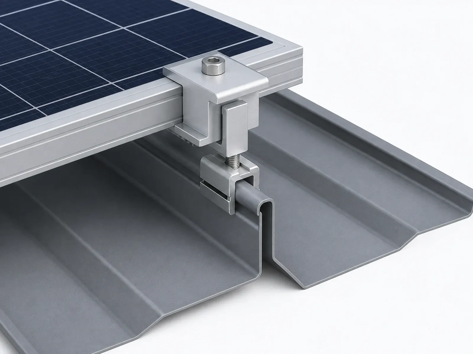
Clamp fixing 3D node illustration

Clamp fixing

Dedicated clamps grip metal-roof seams without penetrating the roof sheet.
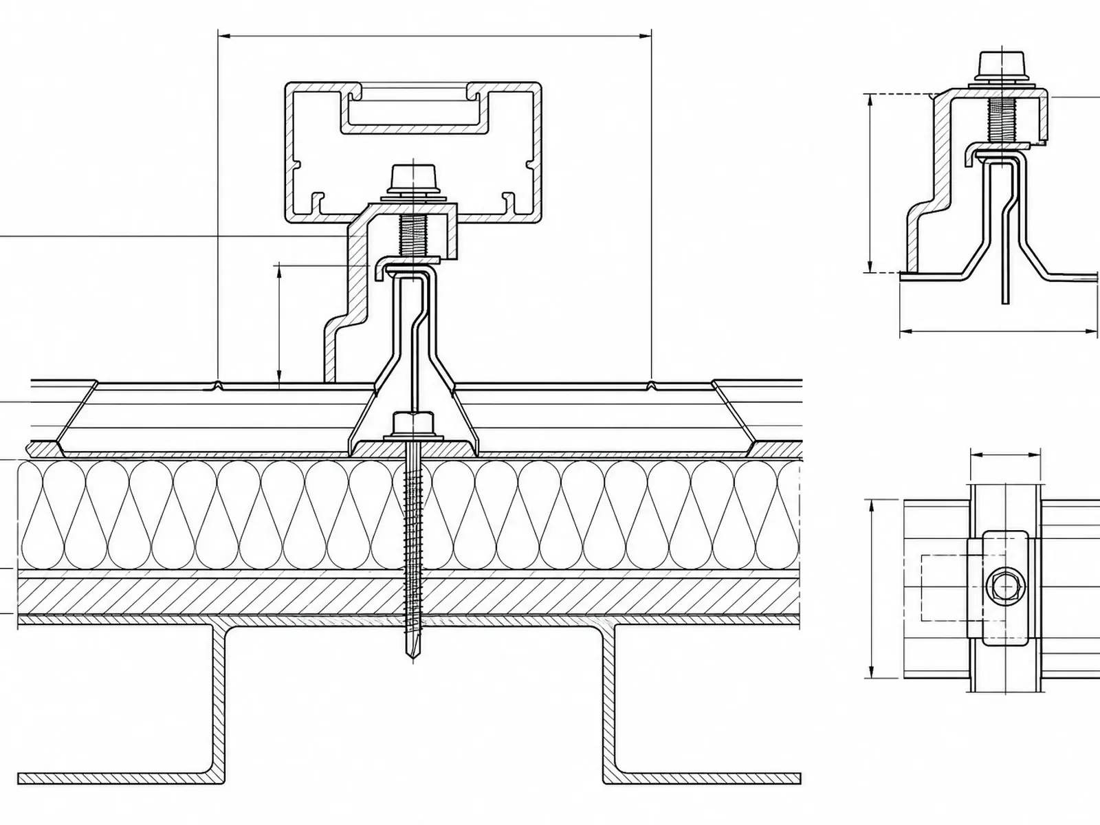
Clamp fixing CAD install drawing
Ballasted node 3D illustration

Ballasted

Concrete or steel ballast provides uplift resistance without roof penetrations, protecting the membrane.
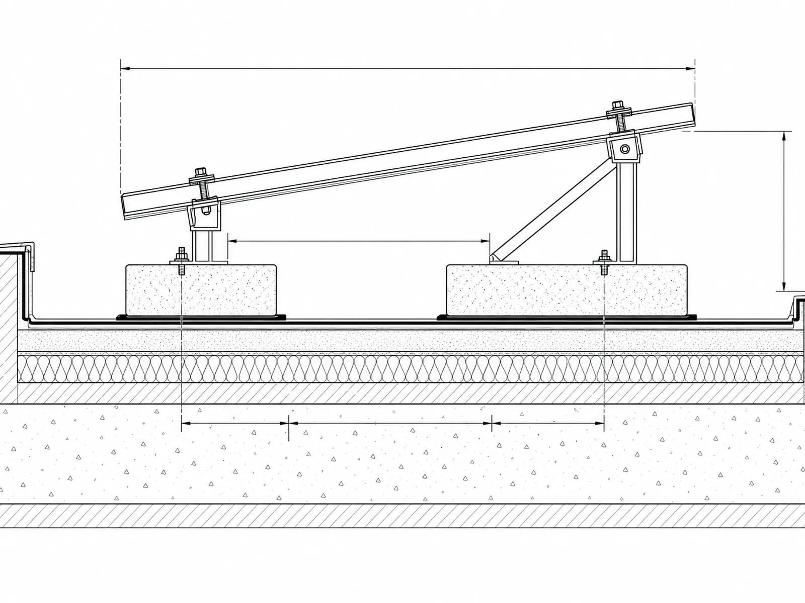
Ballasted CAD install drawing
Mechanical fixing 3D node illustration

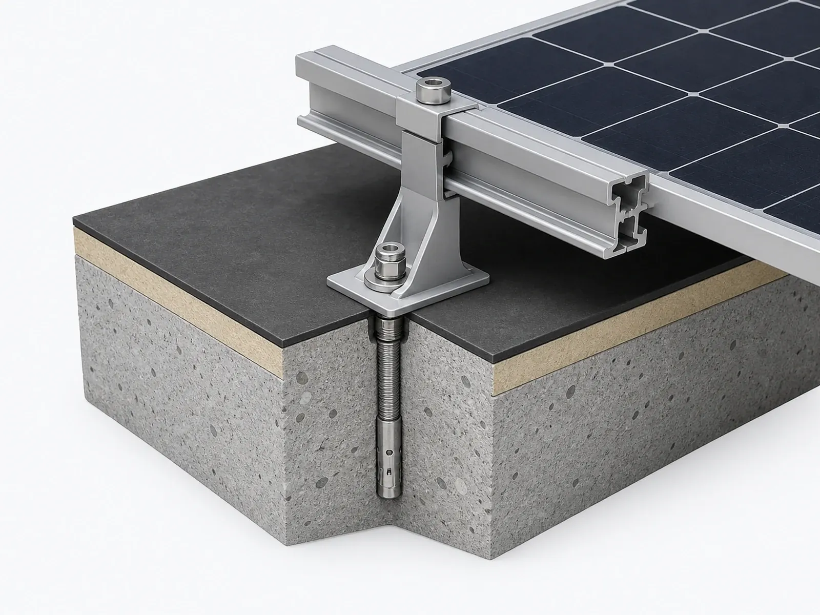
Mechanical fixing

Mechanical anchors into concrete structure for reliable connections.
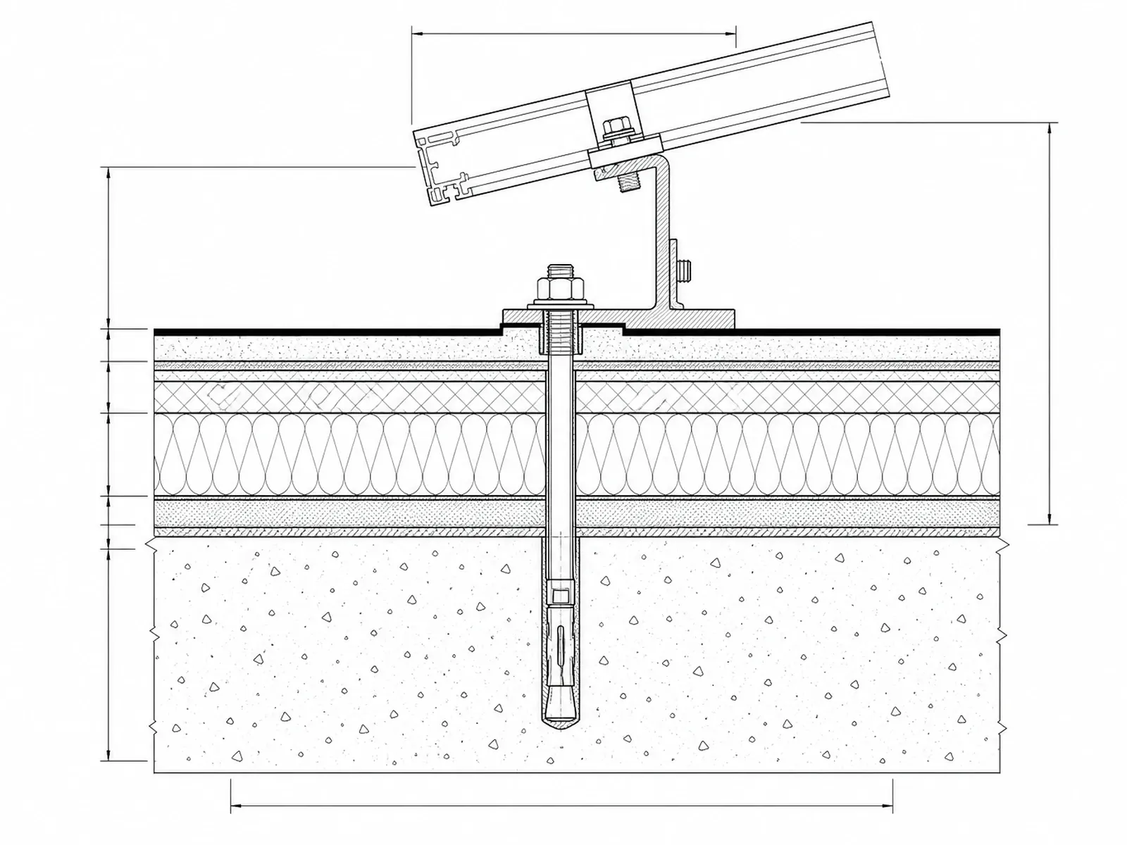
Mechanical fixing CAD install drawing
Custom node 3D illustration

Custom nodes

Custom solutions for special roofs and details with precise adaptation.
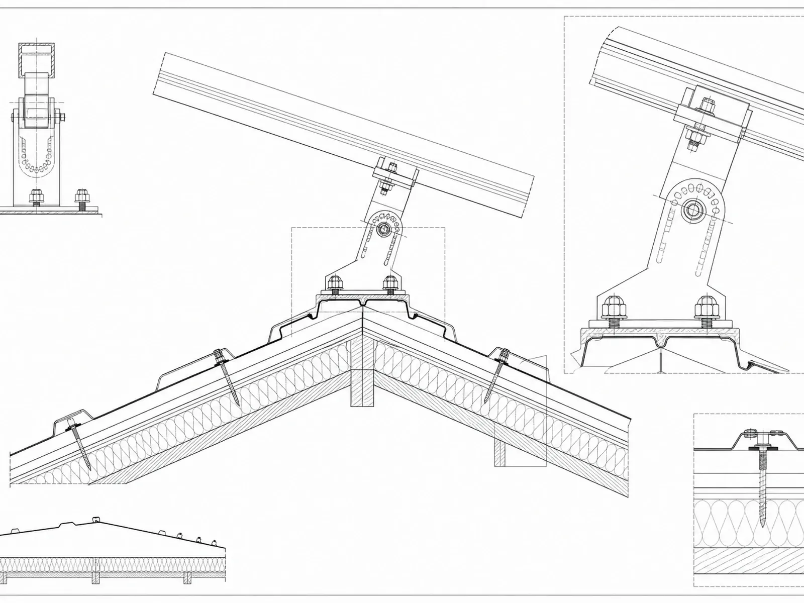
Custom node CAD install drawing

Engineering boundary: Final fixing methods must follow existing structural documents, site survey, waterproofing system, load checks and applicable codes.

ENERGY FLOW

From generation to facility energy use

C&I rooftop PV value depends not only on installed capacity, but also on facility load curves, tariff structure, self-consumption ratio and interconnection conditions.
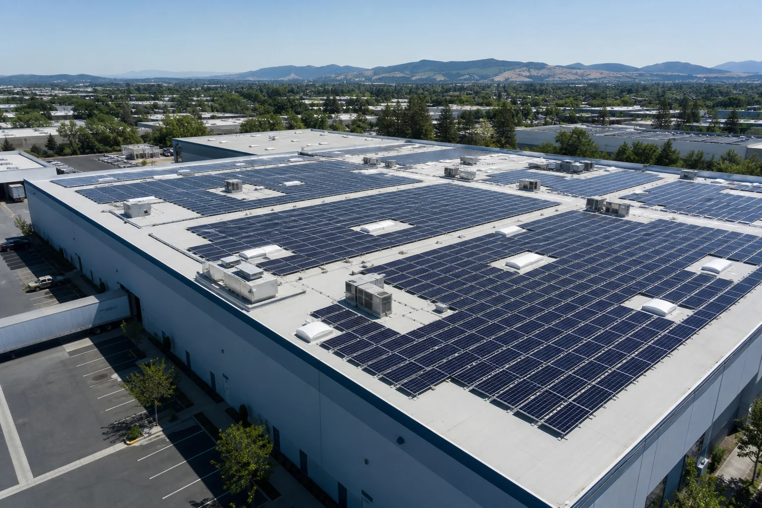
C&I rooftop PV array
01 Rooftop PV DC generation
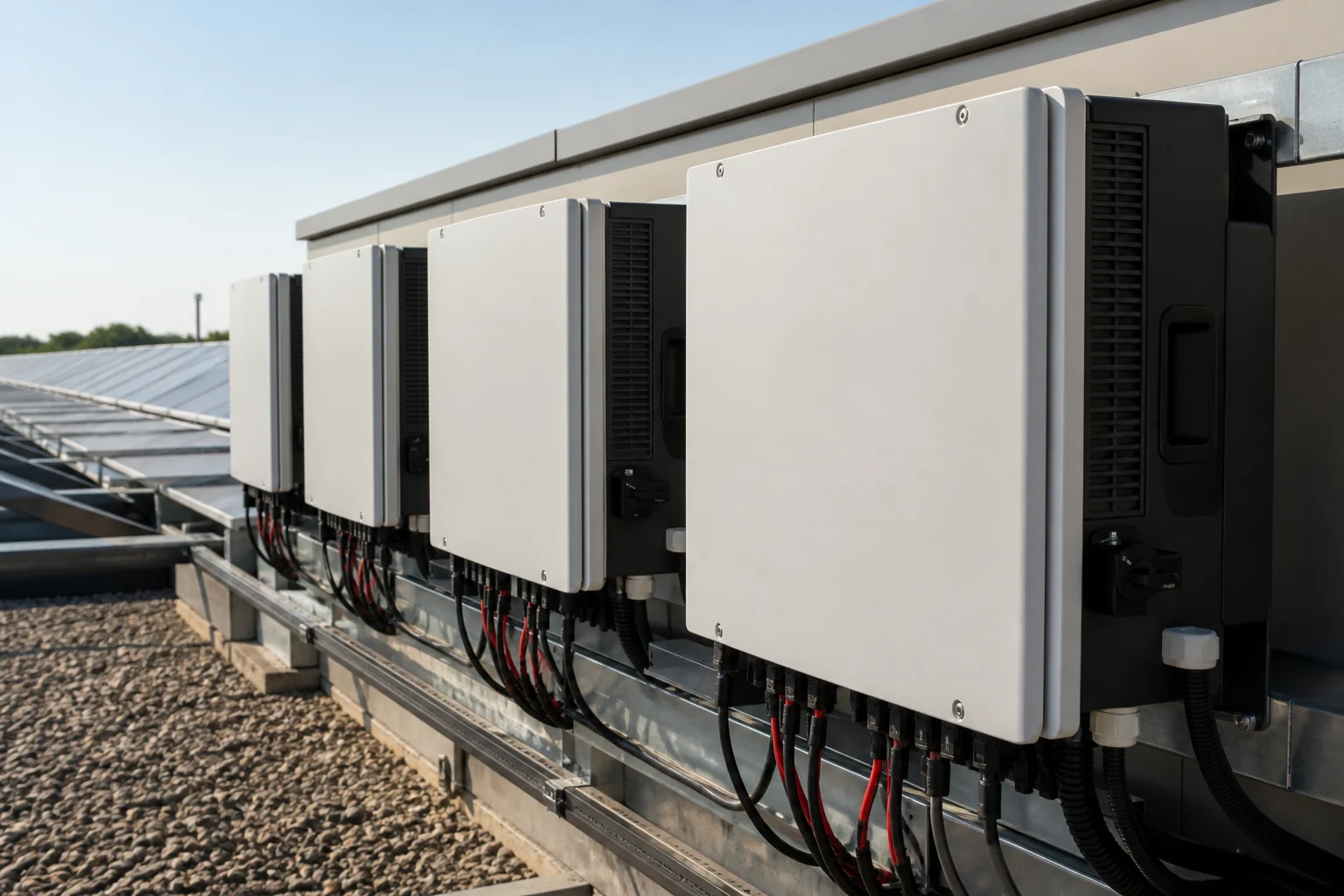
Rooftop PV system and electrical layout
02 Inverter DC to AC conversion
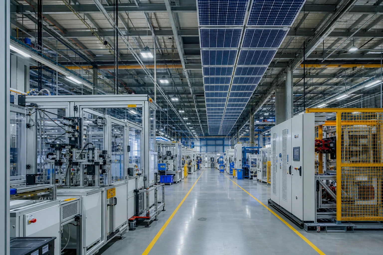
Industrial manufacturing facility energy use
03 Facility load Priority for production use
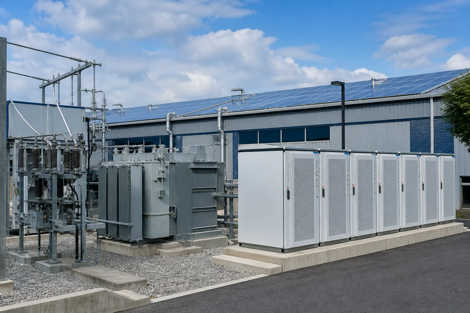
Industrial park grid and storage coordination
04 Grid / storage Coordinated by project conditions
Self-consumptionPeak tariff substitutionExport surplusStorage coordination
TYPICAL DAILY CURVE Typical daily load / PV / storage coordination curve Schematic weekday profile · 15-min synthesized samples
Schematic
Installed capacity 2.50 MWp
Peak load 1.82 MW
Self-consumption 78%
Midday window 10:00–15:00
Typical daily yield 12.6 MWh
Storage sizing 1.0 MWh / 0.5 MW
Facility load PV generation Grid exchange Storage charge/discharge SOC
Midday window 0 400 800 1200 1600 2000 2400 00:00 04:00 08:00 12:00 16:00 20:00 24:00 0 25 50 75 100 Power (kW) SOC (%) Time (h)
PV peak 2.18 MW @ 12:30 Load peak 1.82 MW @ 10:00 Night valley 0.54 MW @ 04:00

Curves illustrate energy flow only and do not represent project yield or revenue.

ENGINEERING DELIVERY

Engineering process from survey to handover

Under no-shutdown or minimized production-impact constraints, connect site information, detailing, manufacturing supply and zoned installation.

Site survey

Survey the site and collect roof conditions

Roof assessment

Assess roof conditions and confirm a feasible approach

Structural review

Review structure to ensure load safety

BIM / layout

Model and arrange arrays to optimize system layout

Mount detailing

Detail the mounts and output fabrication drawings

Manufacture & supply

Standardized production and on-time supply

Zoned installation

Install by zones to keep construction safe

Acceptance & handover

Pass acceptance checks and handover documentation

Construction focus Personnel safetyProduction impactMaterial turnoverRoof protectionConcurrent work

PROJECT SCENARIOS

Project scenarios / engineering cases

These scenarios explain scheme differences under different roofs and buildings — not accepted project references or performance claims.
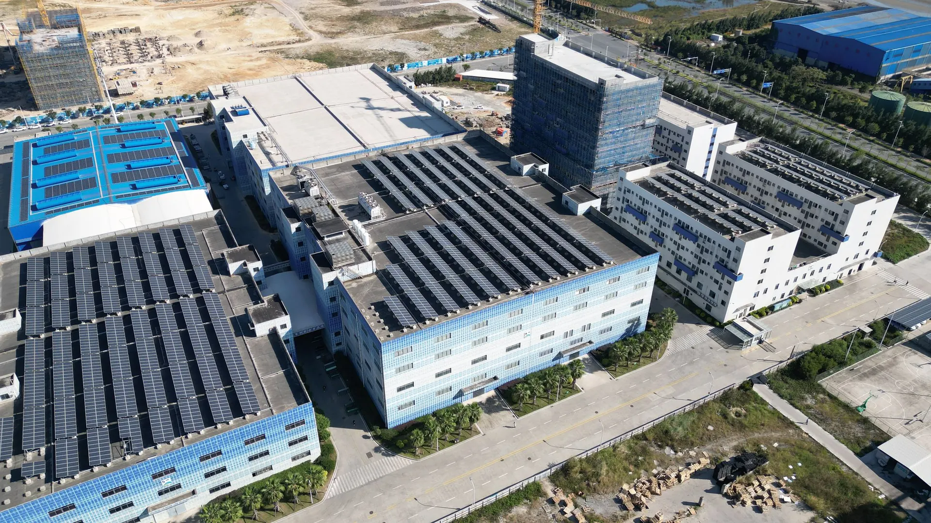
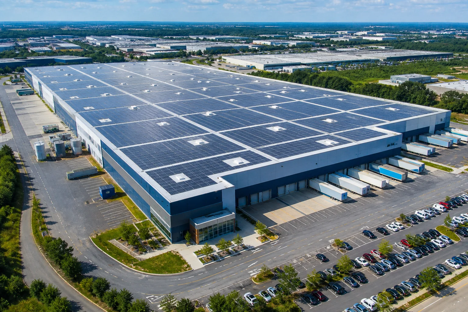
Manufacturing plant scenario MANUFACTURING

Manufacturing plants

Roof type
Metal / standing-seam roof
System approach
Clamp or project-custom nodes
Engineering traits
Large continuous roofs needing skylight and equipment coordination
Logistics warehouse scenario LOGISTICS

Logistics & warehousing

Roof type
Metal roof / concrete flat roof
System approach
Clamp, ballast or mechanical fixing
Engineering traits
Large single footprints with clear fire and O&M corridor needs
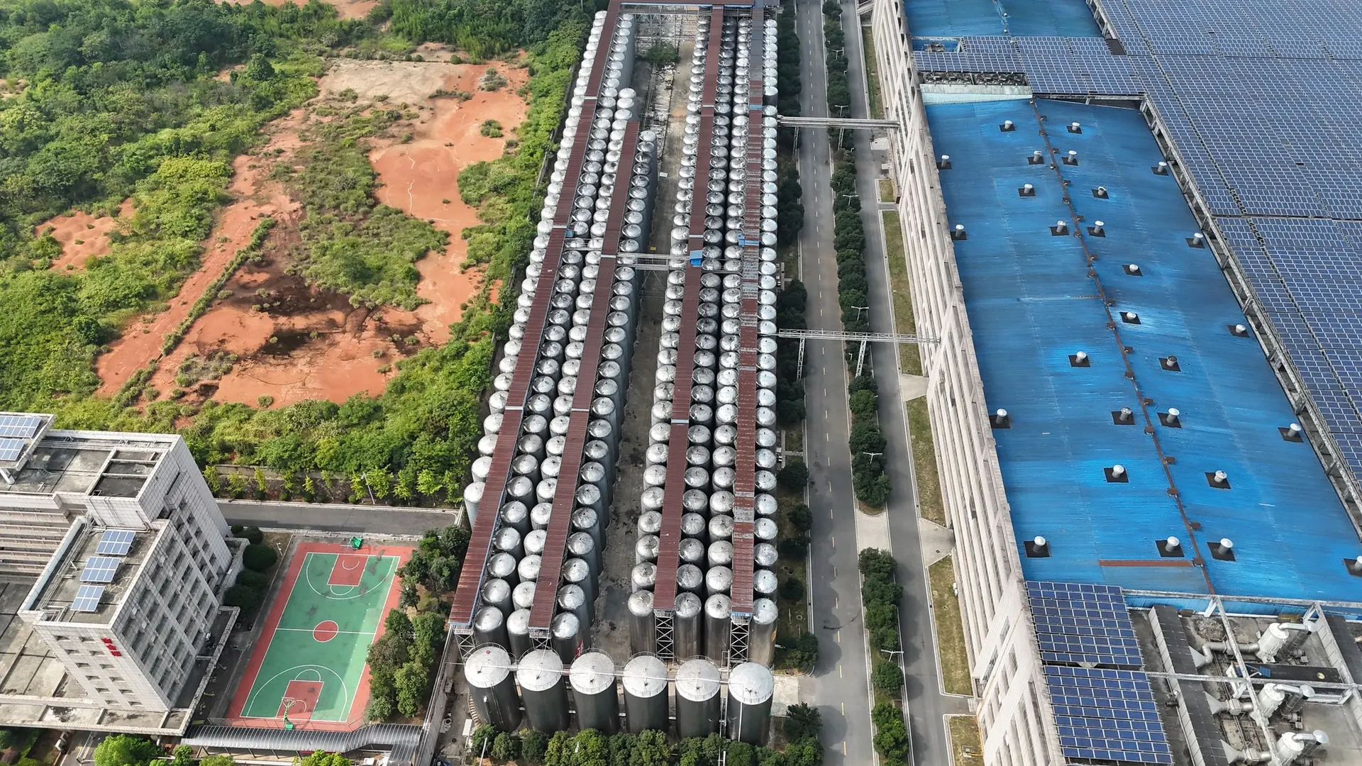
Industrial park scenario INDUSTRIAL PARK

Industrial parks

Roof type
Multiple buildings and roof systems
System approach
Zoned selection with unified detailing
Engineering traits
Coordinate buildings, interconnection paths and install sequence
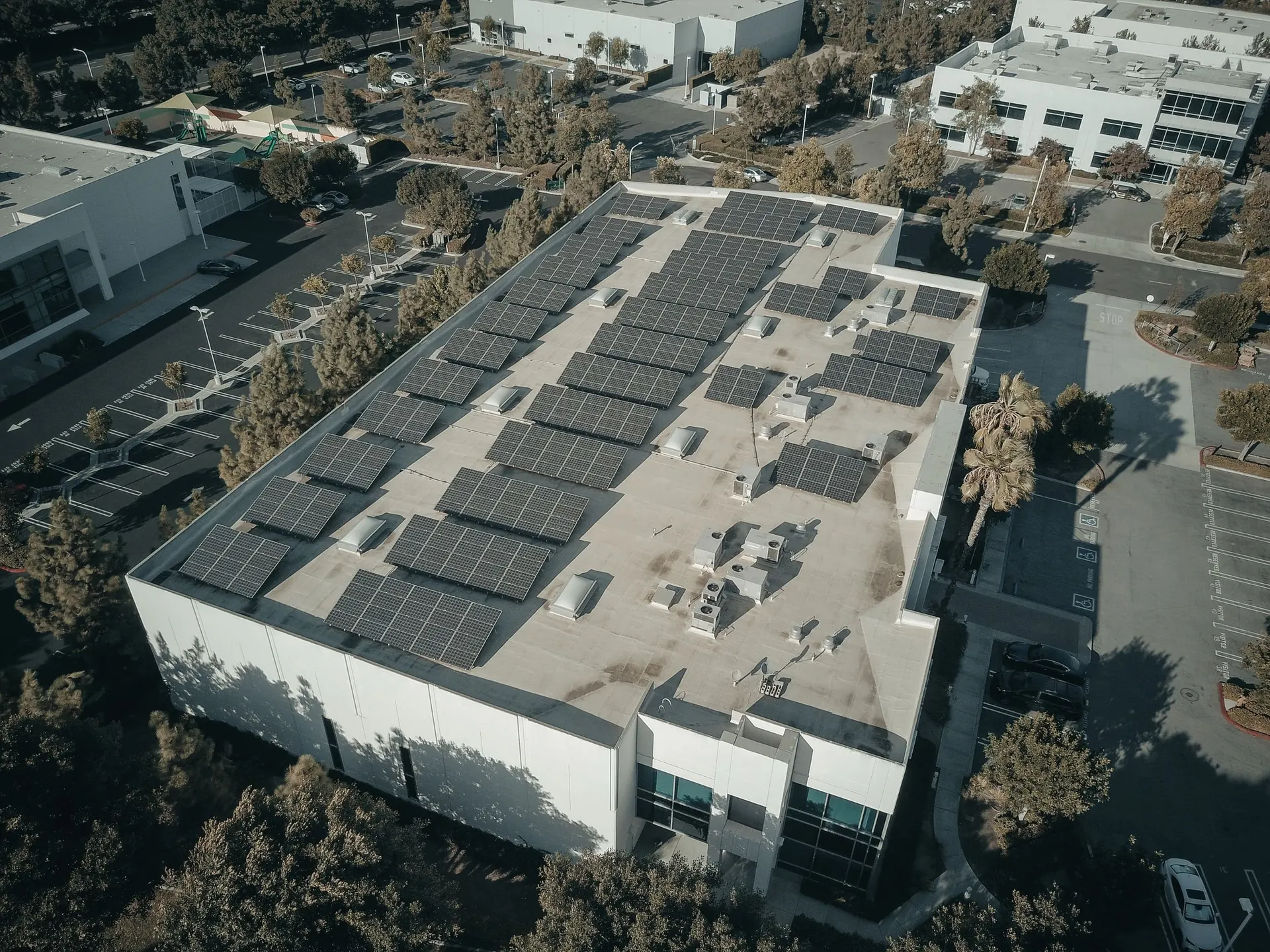
Commercial building scenario COMMERCIAL

Commercial buildings

Roof type
Flat / complex roofs
System approach
Customized to building conditions
Engineering traits
Balance equipment clearances, maintenance, safety and facade interface

Define your PV system from roof conditions

Submit your project intent and we will provide a professional solution pathway and quotation guidance.