

PRODUCTION PROCESS
Production Process
From engineering data and raw materials to finished engineered components.
ENGINEERINGMATERIALFORMINGMACHININGASSEMBLYFINISHED PART
ONE PART · MULTIPLE STATES
One part · multiple states
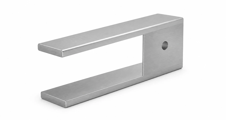
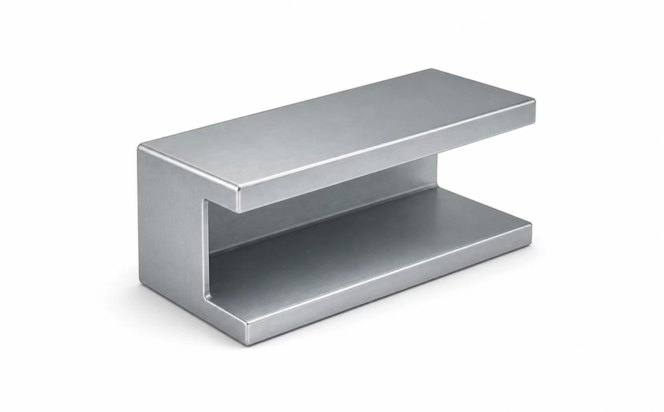
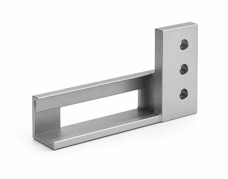
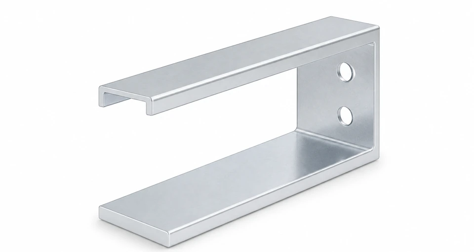
From raw material to finished goods, each process stage creates a visible change.
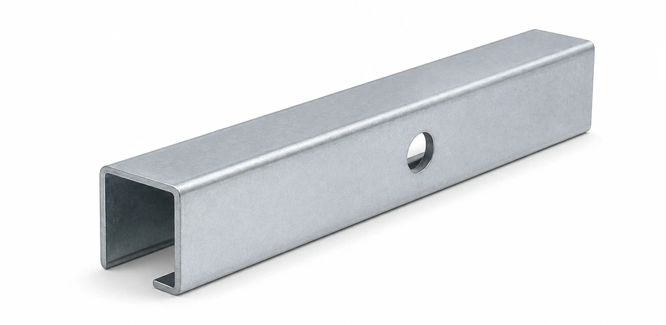
ENGINEERING → MANUFACTURING
Engineering data → manufacturing input
Convert design data into executable manufacturing information; revision status must be explicit in production inputs.
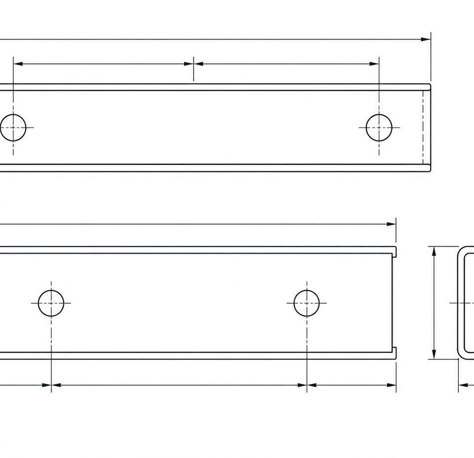
DRAWING Engineering drawing
BOM Bill of materials
ITEMPARTDESCQTY 1—PROFILE—2—PLATE—3—FASTENER—
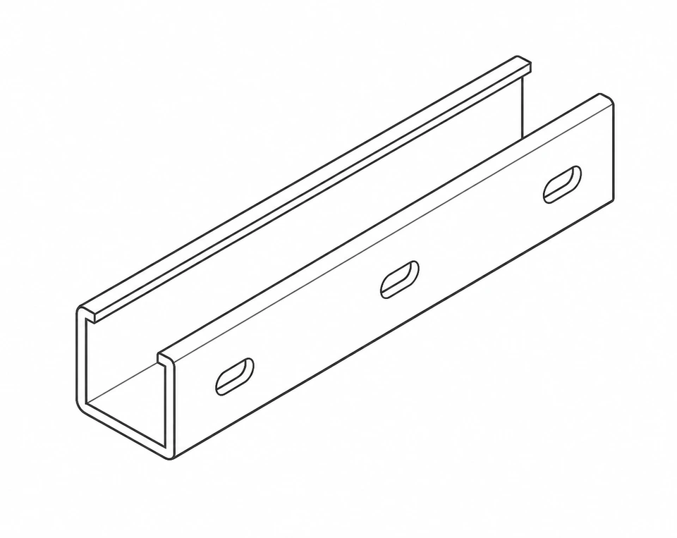
PART DATA Part data
- L: —
- W: —
- H: —
- T: —
- MATERIAL: —
REVISION Revision
REV AREV B CURRENT
PROCESS ROUTE Process route
- Forming
- Punching
- Cut to length
- Machining
- Surface route
- Inspection & Pack
PART ID Part identity
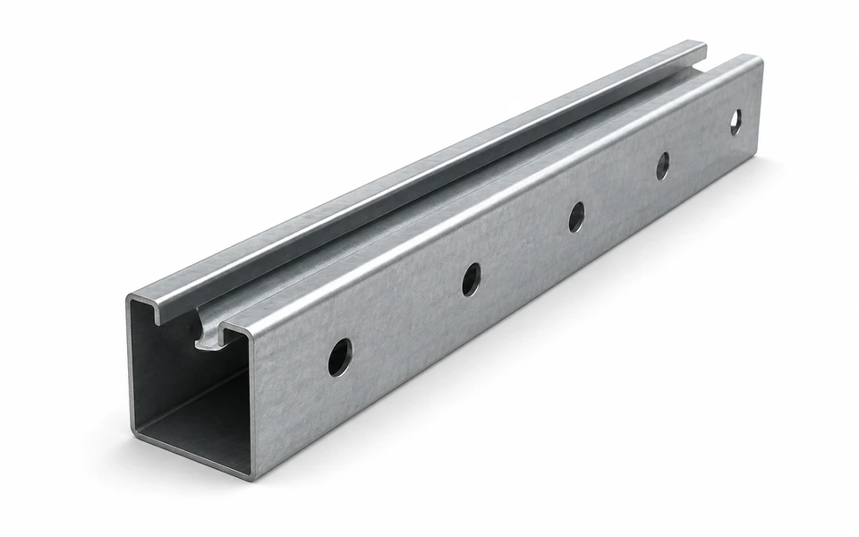
—
ROLL FORMING
Roll forming
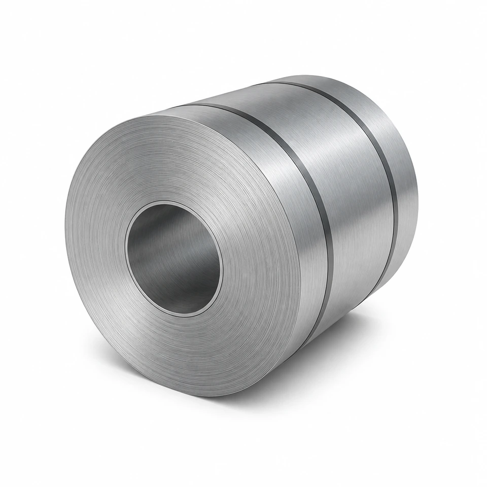
Feed coil or strip through continuous rollers to form the target section, then cut to length for the next process.
RAW MATERIAL Coil / strip
› FEEDING Feed & align
› FORMING Continuous forming
› TARGET PROFILE Target profile
› CUT TO LENGTH Cut to length
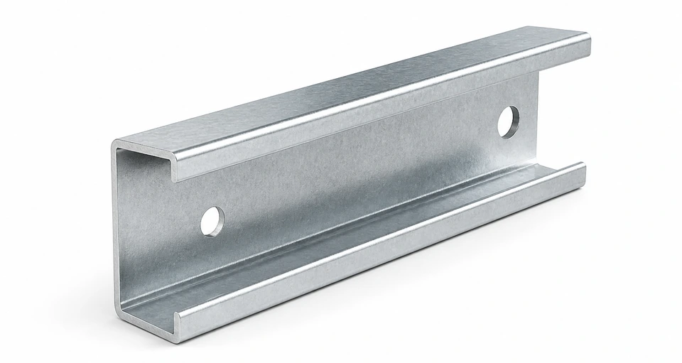
PUNCH · CUT · MACHINING
Punch · cut · machining
Execute hole pattern, pitch, length and end conditions to drawings so parts meet design requirements.
LENGTH (L)
HOLE PITCH (P)
EDGE DISTANCE (ED)
END CONDITION (EC)
SURFACE PROTECTION ROUTE
Surface protection route
Select the suitable protection route from material, service environment, structural design, project requirements and install conditions.
◈ MATERIAL Material ⌁ ENVIRONMENT Environment ⌖ DESIGN Design ▧ PROJECT Project ◇ ASSEMBLY Assembly
PROCESS ROUTE MATRIX
Different parts · different routes
Choose routes by part type, material and application. The matrix shows typical relations only; final routes follow part and project conditions.
| Part type | Example use | Material | Forming | Punch | Cut | Weld | Surface | Pack |
|---|---|---|---|---|---|---|---|---|
| A. PROFILE Continuous profile | PV / SUPPORT | ● | ● | ○ | ● | – | ○ | ● |
| B. PLATE / CONNECTOR Plate / connector | SUPPORT | ● | ○ | ○ | ● | – | ○ | ● |
| C. WELDED ASSEMBLY Welded assembly | SEISMIC / SUPPORT | ● | ○ | ○ | ● | ● | ○ | ● |
| D. PROJECT / NON-STANDARD Project non-standard | PV / SEISMIC | ● | ○ | ○ | ● | ○ | ○ | ● |
● Typical○ Part-dependent– Usually not involved
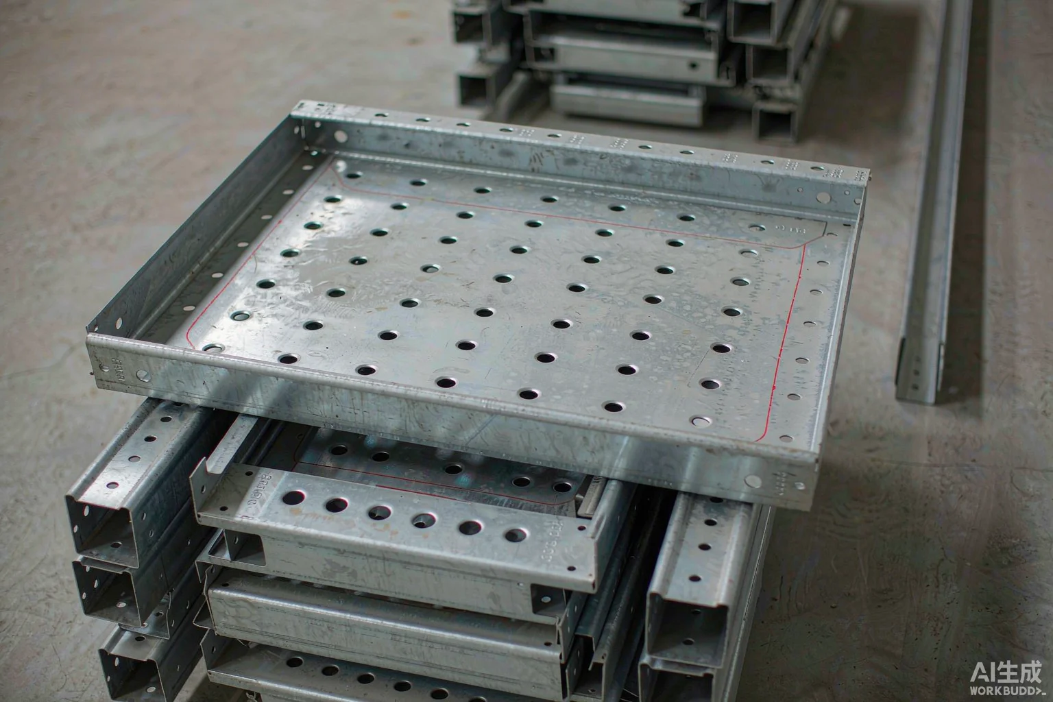
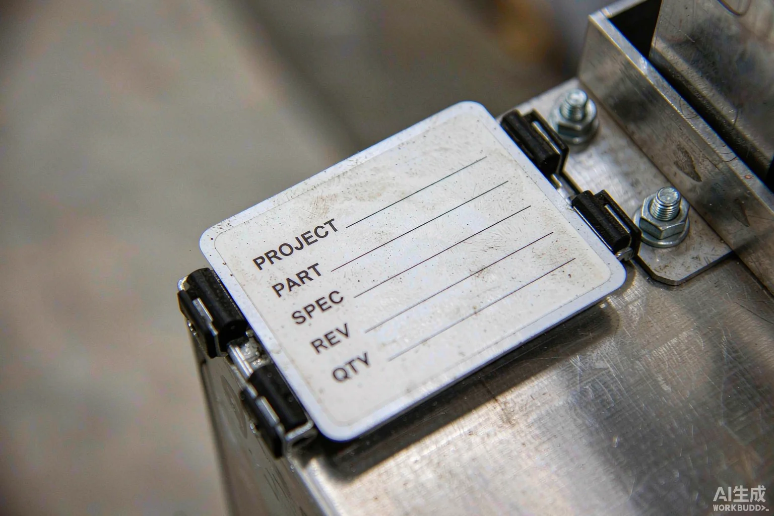
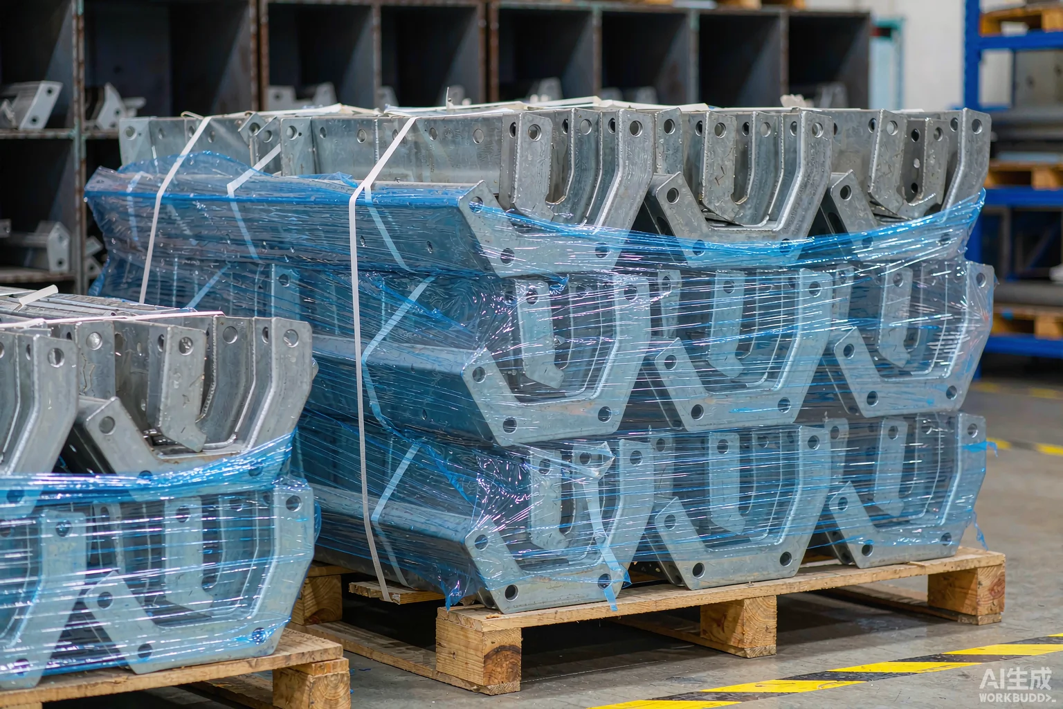
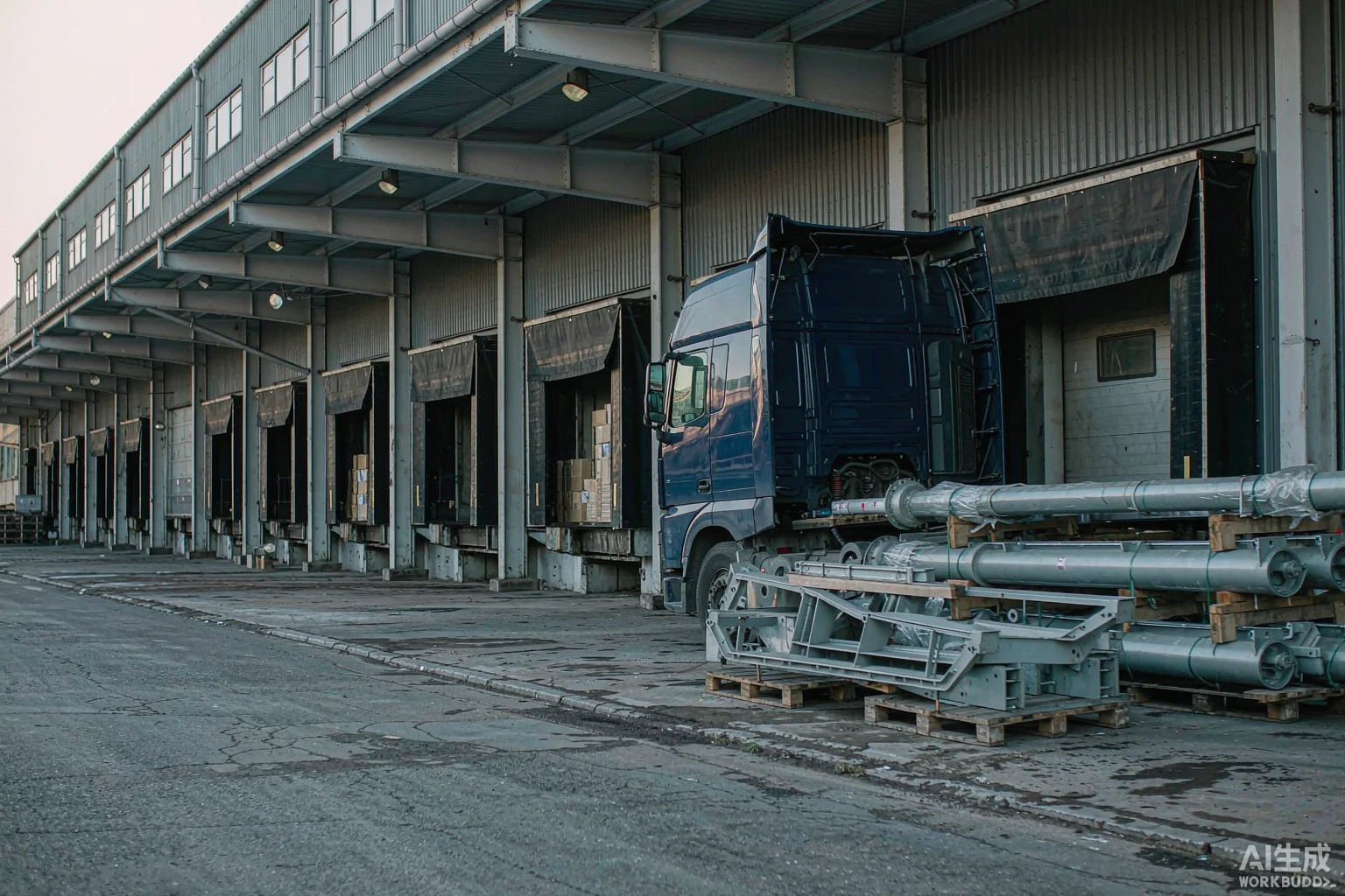
FINISHED PART ORGANIZATION
Manufacturing complete · QC & project kitting
Finished parts are identified, classified, kitted and packed, then handed to quality inspection and delivery.
MANUFACTURING SUPPORT
From drawing to part — confirm the process route first
Submit drawings, BOM, part types and project conditions so engineering and manufacturing can confirm scope and the applicable route.