

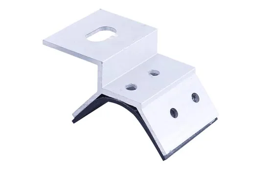
Metal-roof clamp node
The clamp engages the rib or seam and locks to the rail; non-penetrating installation is preferred where applicable.
A clamp-and-rail configuration for trapezoidal, angle-seam and standing-seam metal roofs, reducing unnecessary roof penetration.
[PV-ROOF-01] is the standard supply and fast-production configuration in this series, covering the first typical engineering boundary for rooftop PV mounting.
The system uses matched clamps and aluminum rails for common roll-formed roof profiles. Non-penetrating engagement at the rib or seam is preferred to protect the existing waterproofing system.
It is intended for distributed PV on commercial and industrial factories, warehouses and similar metal roofs; clamp type, rail span and anchorage spacing follow roof review and uplift calculations.
The typical configuration consists of aluminum rails, matched metal-roof clamps, 6005-T5 rails and 304 stainless clamp bolts.
Recommended reference tier: SYS-PV-R01-S, clamp spacing 0.8–1.2 m, light-duty structure; other tiers are listed below.
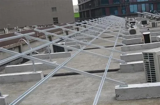
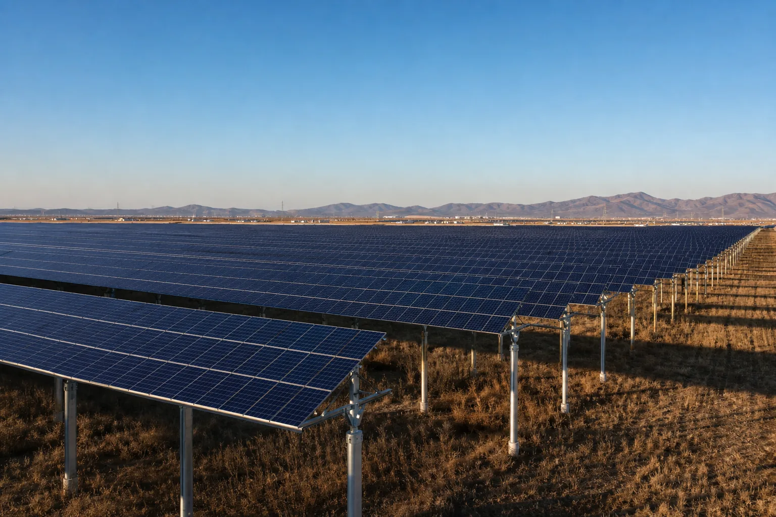
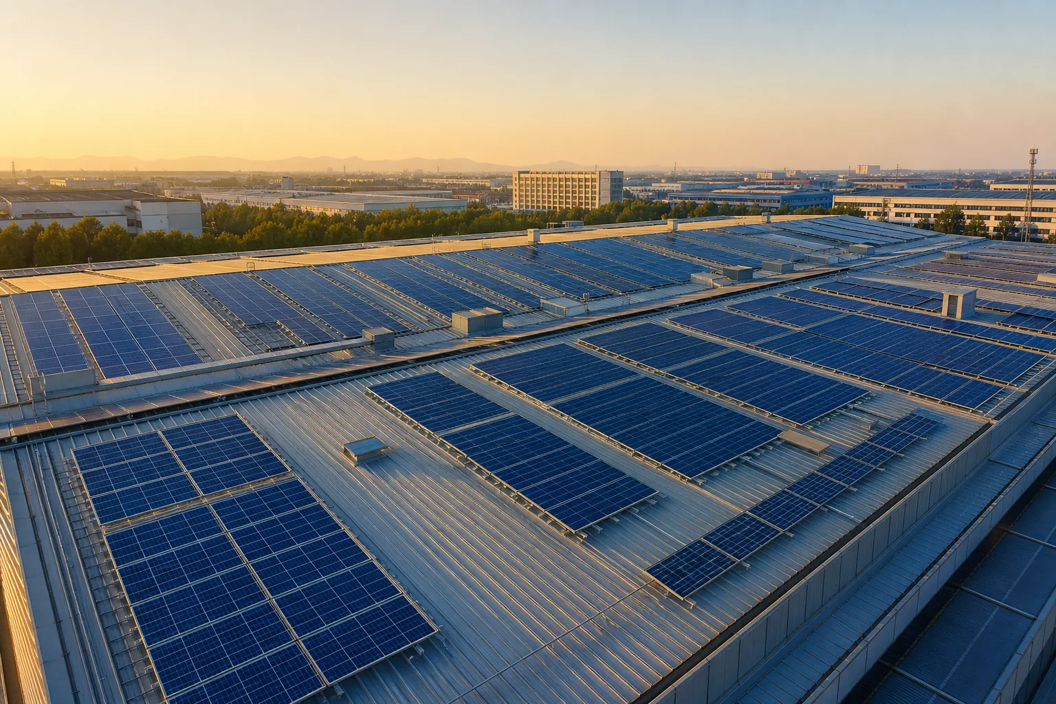
Typical node illustrations and notes; detailed project nodes follow the calculation package and construction drawings.
The clamp engages the rib or seam and locks to the rail; non-penetrating installation is preferred where applicable.
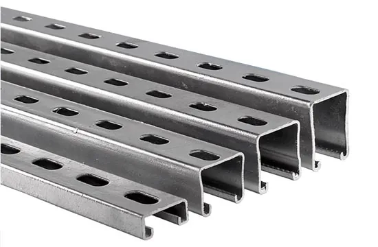
Rail joiners, bonding washers and end and mid clamps follow module frames and torque requirements.
Key parameters and engineering boundaries for the Metal-Roof Rooftop Mount; final values follow project calculations and shop drawings.
These public reference values are for Metal-Roof Rooftop Mount (PV-ROOF-01). Load, layout and interface conditions not listed here must be confirmed during project review.
| Model | Clamp spacing | Structure | Typical use | Notes |
|---|---|---|---|---|
| SYS-PV-R01-S | 0.8–1.2 m | Light-duty | Small array / low wind | Standard |
| SYS-PV-R01-M | 0.6–1.0 m | Standard | Typical C&I metal roof | Most common |
| SYS-PV-R01-L | 0.5–0.8 m | Densified | High uplift | Check purlins |
| SYS-PV-R01-H | By calculation | Reinforced | Aging / thin panel roof | Structural inspection |
These are typical variant tiers. Final sections, spacing and connections must be confirmed in the project structural calculation package.
The preferred use case, engineering boundary and distinction from other products in the same category.
Answers for the structure, interface and document requirements of Metal-Roof Rooftop Mount (PV-ROOF-01).
PV-ROOF-01 uses aluminum rails and matched metal-roof clamps. Wind, snow, seismic and installation interfaces must be checked for the project.
The common interface is non-penetrating clamps, with penetration only after review. Capacity, waterproofing and anchorage boundaries are confirmed during detailing.
The typical configuration uses 6005-T5 rails and 304 stainless clamp bolts. Coastal, chemical or corrosive environments require a separate corrosion review.
Structural and connection design should satisfy roof dead-load reserve, uplift and purlin spacing under the governing load combinations.
The listed tiers are typical references; final sections, spacing and connections must be confirmed in the project structural calculation package.
The structural form and interfaces are reviewed during detailing against the roof, service access and module boundaries.
Datasheets, drawings, models and inspection reports for Metal-Roof Rooftop Mount (PV-ROOF-01) can be provided for project requirements.
No general downloadable file is placed on this page. Submit the project conditions and we will provide the applicable datasheet, CAD drawing or BIM model by model and engineering boundary.