
Matched node delivery
Drive seats, tube joints, purlin seats and locks are matched to the SYS-PV-T system to reduce field mix-ups.
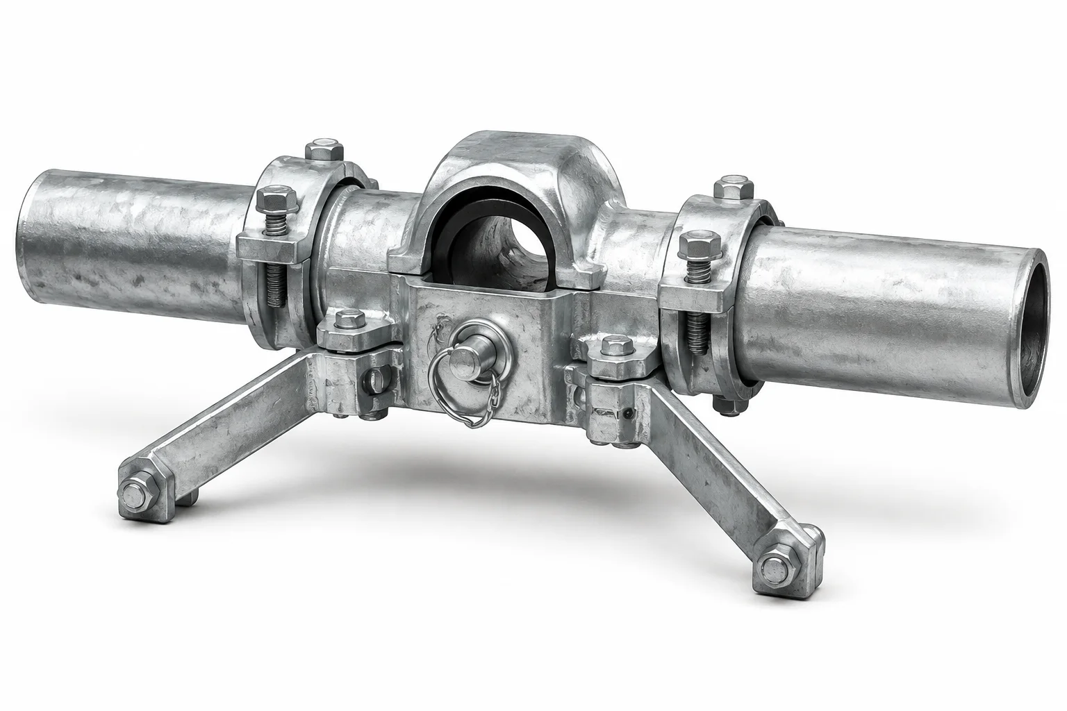
Covers drive, post, purlin and connection nodes with matched kit delivery.
[PV-TRACK-02] is positioned for longer spans or higher-load boundaries as the second typical tier in the single-axis tracker series.
The kit standardizes drive seats, main-tube joints, purlin seats, lock pins and bonding accessories for factory preassembly and fast field installation.
Connector sizes follow main-tube sections and drive models; bulk projects can be supplied by drive-zone numbering.
Typical materials are Q355B / Q235B steel parts with grade 8.8 high-strength bolts; hot-dip galvanizing is standard, with dacromet optional on critical parts.
Drive seats, tube joints, purlin seats and locks are matched to the SYS-PV-T system to reduce field mix-ups.
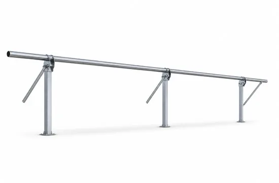
Select by slew / push-rod and torque-tube bending zones instead of one generic connector.
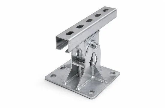
Tube joints, bearing locks and bonding interfaces can be reviewed against project drawings and preassembled.
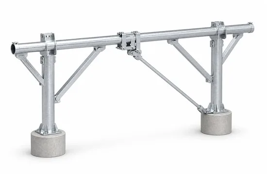
RFQ, BOM, zone numbers and drawings share PV-TRACK-02 / SYS-PV-T02 identification.
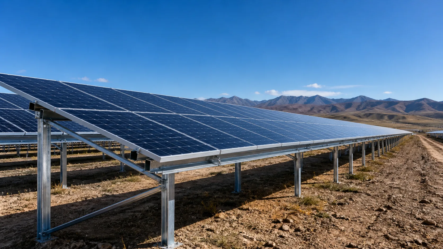
For single-axis tracker arrays, focused on the relationships among torque tube, drive, bearings and control.
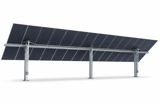
Transfers rotation and bending; check SYS-PV-T02-J in bending zones.
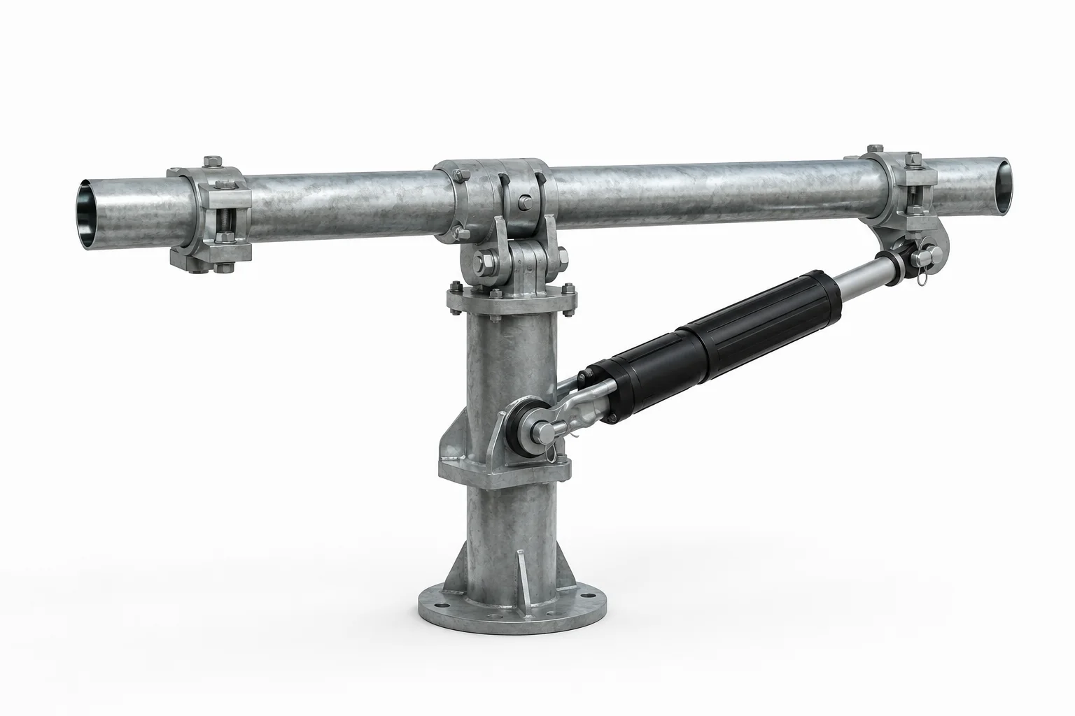
Slew drive or linear actuator; check SYS-PV-T02-D at the mounting node.
Supports rotation and carries mechanical lock loads in stow.
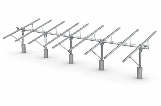
Secure modules to the tube; review layout and wind loads.
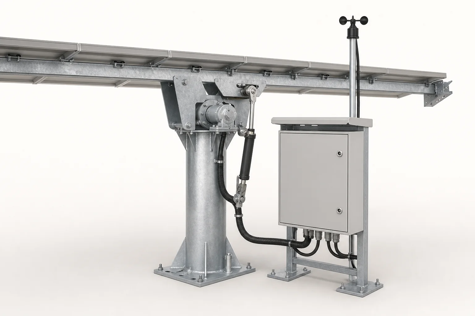
Strategy execution and communications confirmed in electrical design.
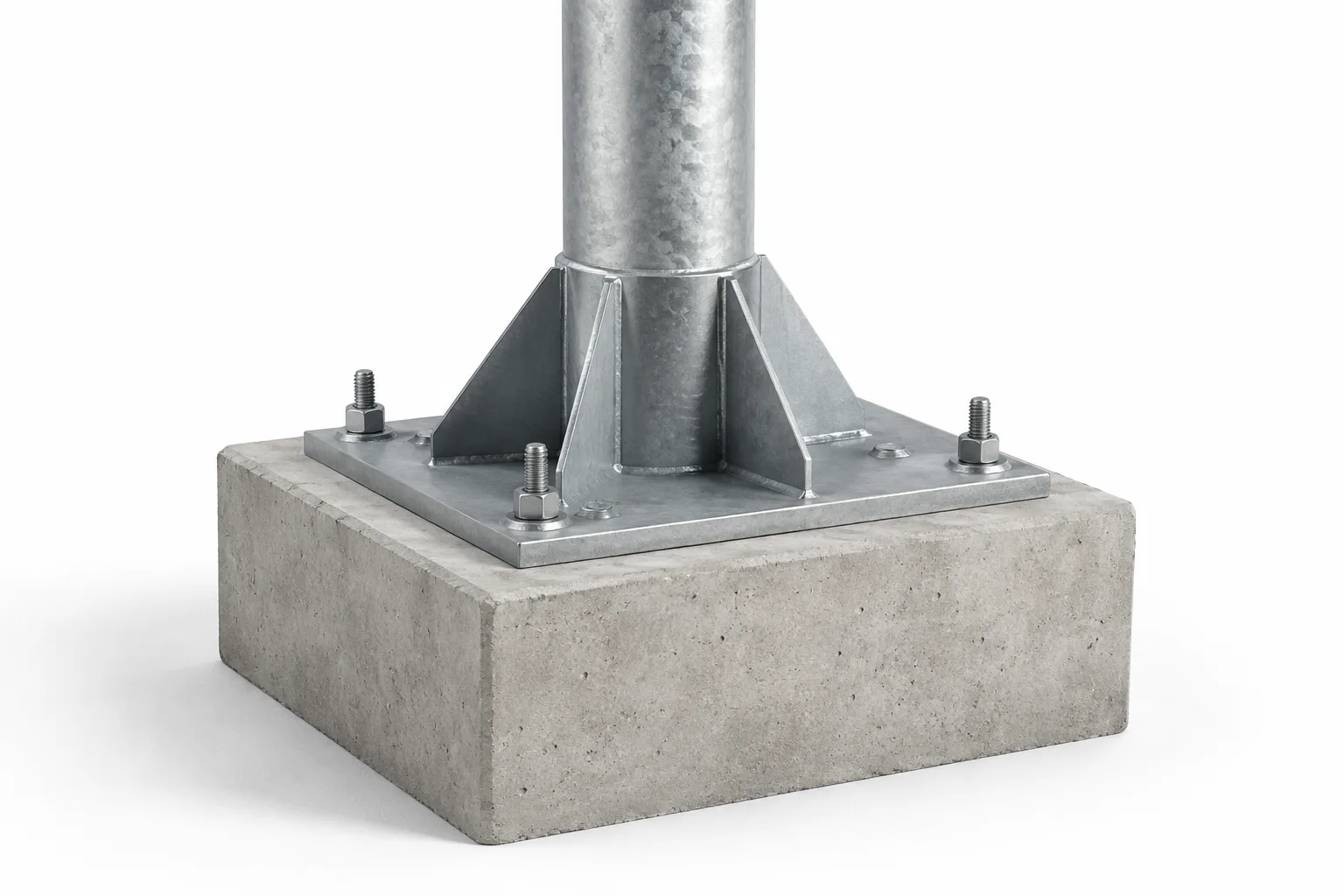
Pile / concrete foundations checked with drive loads.
Typical node illustrations and notes; detailed project nodes follow the calculation package and construction drawings.
Two tube sections are joined by flange or sleeve to keep torsional stiffness and bending transfer; prefer SYS-PV-T02-J in bending zones.
The bearing seat transfers rotation and load; mechanical locking must remain reliable in high-wind stow and match the drive seat kit.
Purlin seats transfer module loads into the tube; spacing and uplift are reviewed and supplied with the SYS-PV-T kit.
Specification layer merges published live-site facts with v4.1 engineering control and data-status columns; final values follow project calculations and shop drawings.
| Parameter | Value / reference | Engineering control | Data status |
|---|---|---|---|
| Product code | PV-TRACK-02 | Identify RFQ, BOM and drawings consistently | Published product code |
| Reference system | SYS-PV-T02 | Confirm by project drawings / calculations | Published series reference |
| Typical parts | Drive seat, tube joint, purlin seat, lock parts | Match drive zones and tube sections | Published |
| Structural form | Drive / post / purlin / connection kit | Confirm by project drawings / calculations | Published / standardized |
| Typical materials | Q355B / Q235B steel, grade 8.8 HS bolts | Confirm by drawings / BOM | Published |
| Surface finish | Hot-dip galvanizing; dacromet optional on critical parts | Confirm by corrosion class | Published |
| Matched drives | Slew drive or linear actuator by system | Select with drive capacity and row length | Published |
| Delivery | Standard parts + zone-numbered kits | Bulk supply by drive-zone numbering | Published |
| Tracking angle | By latitude, yield strategy and mechanical limits | Check control strategy / drive stroke | Project-confirmed |
| Foundation interface | Pile / concrete / project foundation | Check geology, uplift and drive loads together | Project-confirmed |
| Protection strategy | Stow / lock / damping by model and control strategy | Confirm by drawings / calculations | Published / standardized |
| Design inputs | Latitude, layout, wind/snow, control, geology and row length | Confirm by drawings / calculations | Published / standardized |
Public reference values for Tracker Connection Kit (PV-TRACK-02) merged with the v4.1 specification layer. Unpublished engineering values remain project-confirmed.
| Model | Part set | Matched to | Typical use | Notes |
|---|---|---|---|---|
| SYS-PV-T02-D | Drive seat kit | Slew / push-rod | Drive mounting node | Most common |
| SYS-PV-T02-J | Main-tube joint | Torque tube / beam | Tube splicing | Check bending zone |
Published live-site tiers. Other series tiers are on the category comparison table; final values follow the project structural package.
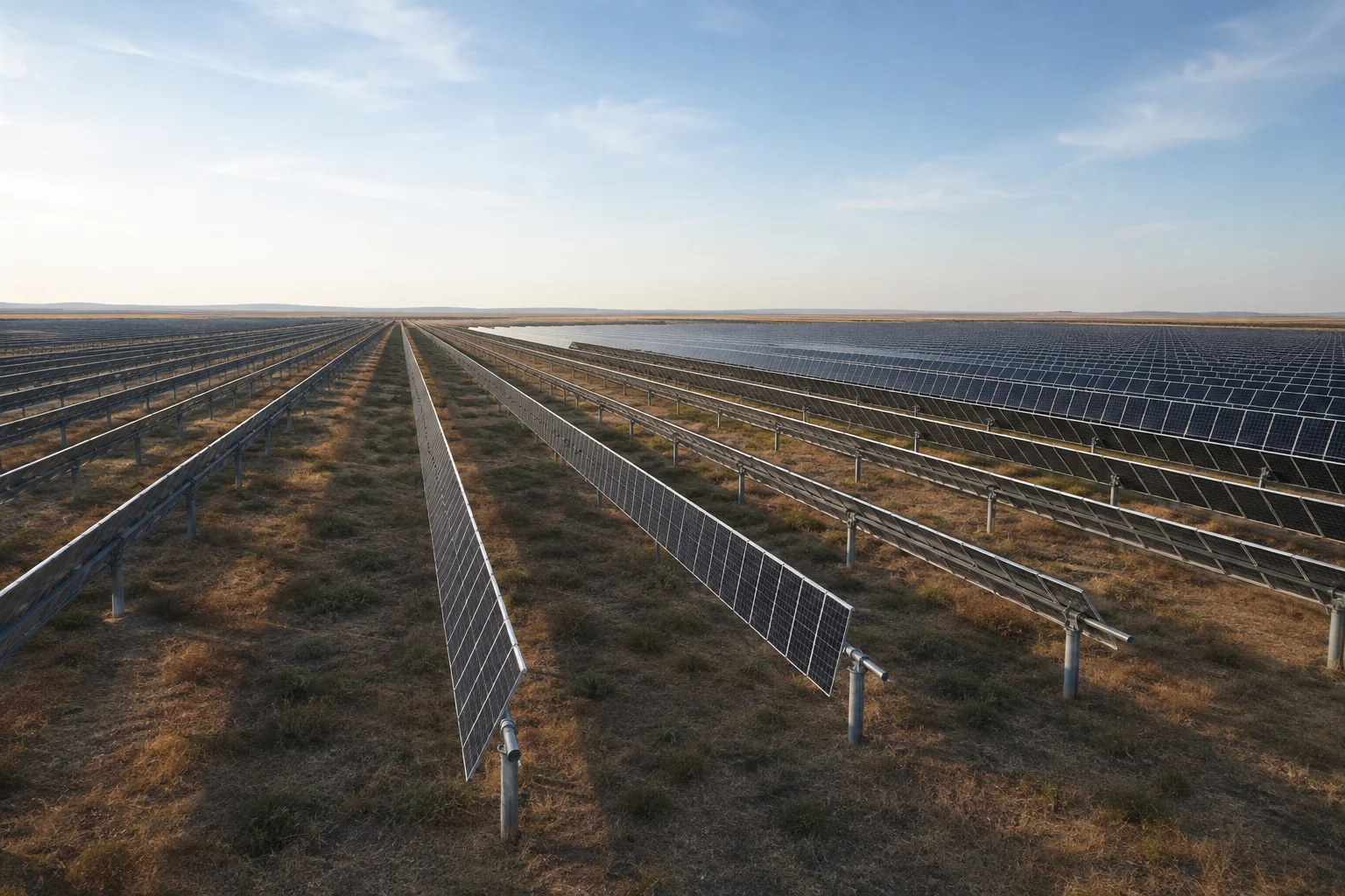
Choose single or multi-drive layouts by row length, terrain and drive capacity; supply connectors by zone numbers.
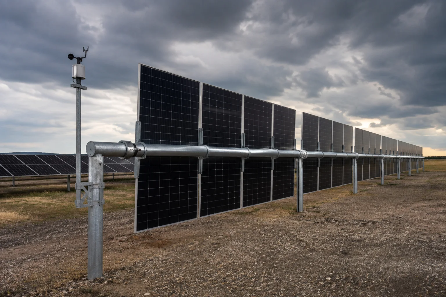
High wind, ice/snow or maintenance modes need explicit stow attitude and mechanical lock logic.
Controller, anemometer, communications and SCADA interfaces are confirmed in electrical design.
Preferred use case, engineering boundary and distinction from other products in the same category.
Answers for the structure, interface and document requirements of Tracker Connection Kit (PV-TRACK-02).
It focuses on matched connection nodes—drive seats, tube joints, purlin seats and locks—rather than a full tracker structure. Use PV-TRACK-01 / 03 when the main constraint is full-array layout or dual-row shared tubes.
At least tube section, drive type (slew / push-rod), row length, design wind speed, slope / terrain, control interface and foundation form. Object size and structural form directly affect nodes, specs and BOM.
Typical configuration uses Q355B / Q235B steel, grade 8.8 bolts and hot-dip galvanizing; critical parts may use dacromet. Coastal, chemical or corrosive sites need a separate corrosion upgrade.
Confirm tube-joint bending zones, drive seats, bearing locks, installation interfaces and site clearance. Page illustrations do not replace project calculations and approved drawings.
Connection and lock design for PV-TRACK-02 should satisfy drive torque, tube bending, stow lock and foundation reaction combinations.
SYS-PV-T02-D / SYS-PV-T02-J are published reference tiers; final sections, holes, bolt grades and corrosion protection follow the project package and BOM.
Unpublished values such as tracking angle and foundation sizes remain project-confirmed and must not be treated as final from the webpage.
Datasheets, drawings, models and inspection reports for Tracker Connection Kit (PV-TRACK-02) can be provided for project requirements.
No general downloadable file is placed on this page. Submit the project conditions and we will provide the applicable datasheet, CAD drawing or BIM model by model and engineering boundary.
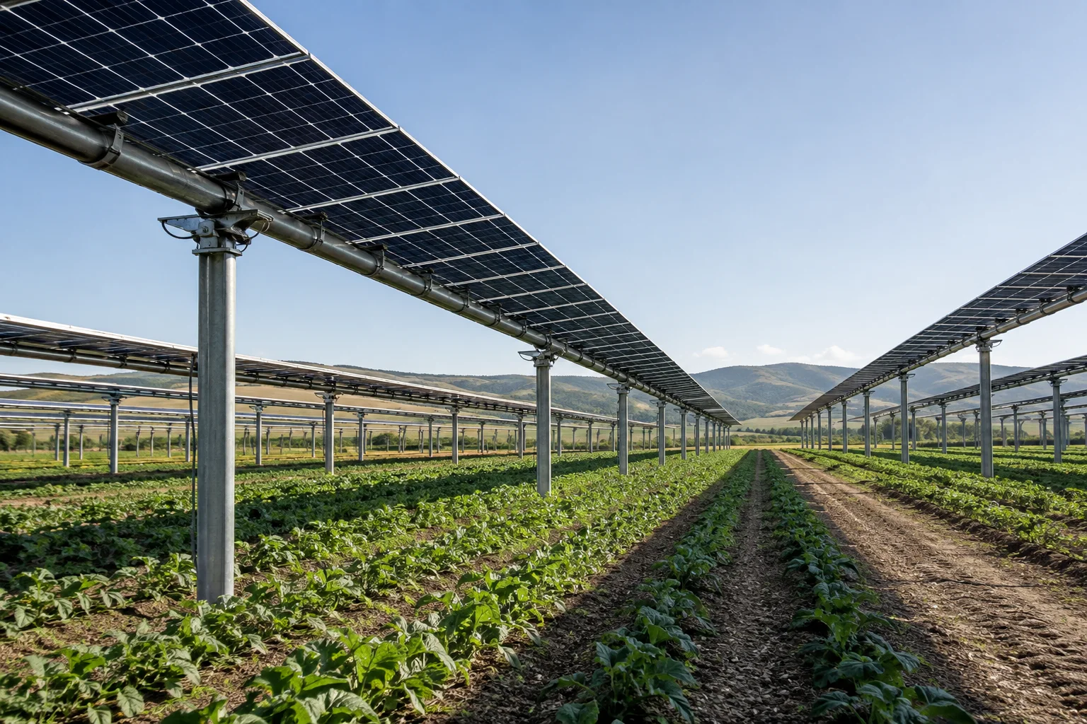
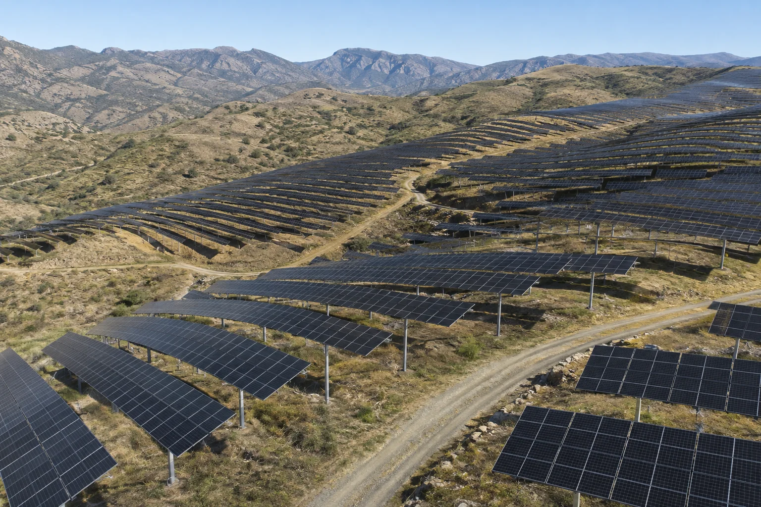
Submit tracker-specific conditions to match drive zoning, connector tiers and protection strategy.